Eureka AIR delivers breakthrough ideas for toughest innovation challenges, trusted by R&D personnel around the world.

Cloth dyeing machine

A cloth dyeing machine and cloth feeding technology, which is applied in the field of cloth dyeing machines, can solve the problems of affecting the dyeing effect of the cloth and the difficulty of dyeing the cloth, and achieve the effects of improving the dyeing effect, reducing energy consumption, and rationally utilizing kinetic energy

Active Publication Date: 2019-01-04
SHAOXING UNIVERSITY
View PDF2 Cites 0 Cited by
  • Summary
  • Abstract
  • Description
  • Claims
  • Application Information

AI Technical Summary

Problems solved by technology

[0002] Exhaust dyeing is a commonly used method in the dyeing process of cloth. In the existing exhaust dyeing process, the cloth is usually directly immersed in the dyeing vat, and the cloth is allowed to absorb the dye in the dyeing vat to realize dyeing on the cloth; a kind of cloth dyeing machine disclosed in Chinese patent CN108265446A, The solid dye settled at the bottom of the tank can be stirred by the liquid stirring device, suspended into the dye liquor and redissolved to improve the utilization rate of the dye; however, when the dye liquor is stirred, air bubbles are injected into the dye liquor, so that There is gas in the dye solution, which affects the dyeing effect on the fabric, and the fabric is not easy to color

Method used


Image

  • Cloth dyeing machine
  • Cloth dyeing machine
  • Cloth dyeing machine

Examples


Embodiment Construction

[0025] In order to enable those skilled in the art to better understand the solutions of the present invention, the technical solutions in the embodiments of the present invention will be clearly and completely described below in conjunction with the drawings in the embodiments of the present invention. Obviously, the described embodiments are only It is a part of embodiments of the present invention, but not all embodiments. Based on the embodiments of the present invention, all other embodiments obtained by persons of ordinary skill in the art without making creative efforts shall fall within the protection scope of the present invention.

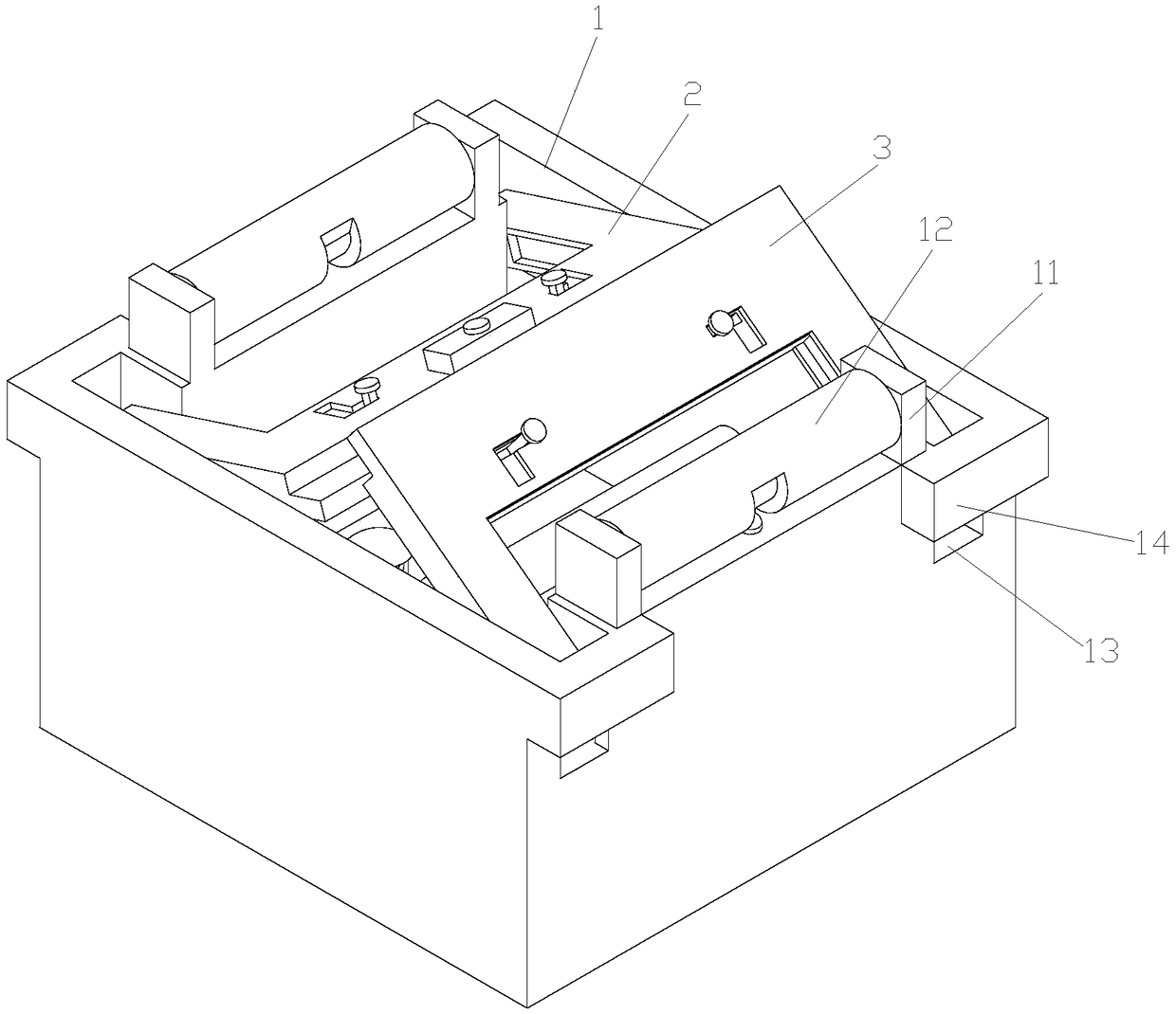
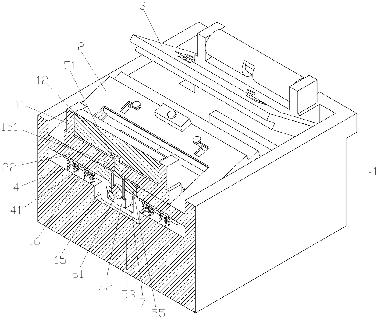
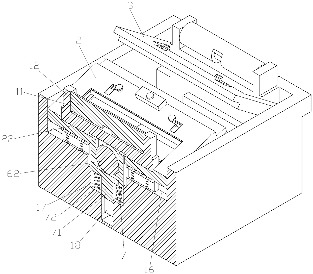
[0026] Such as Figure 1-10 As shown, a cloth dyeing machine includes a cloth dyeing pool 1, a mounting plate 11 located on the dyeing pool 1 and a cloth feeding shaft 12 located on the mounting plate 11, and the cloth feeding shaft 12 is The two groups are respectively located on both sides of the top of the dyeing pool 1, and one cloth...


PUM


Abstract

The invention discloses a cloth dyeing machine comprising a dyeing pool, a mounting plate arranged on the dyeing pool and feeding shafts arranged on the mounting plate. Two groups of feeding shafts are arranged at the two sides of the top of the dyeing pool. A heating block is arranged on the inner wall of the dyeing pool; a rotating roller is arranged inside the dyeing pool and is connected to the inner wall of the dyeing pool in a rotating manner. The cloth dyeing machine is characterized in that mounting grooves are formed in the top of the dyeing pool; the two groups of mounting grooves are arranged at the two sides of the feeding shafts respectively; a first cover and a second cover are arranged in the two groups of mounting grooves respectively and are movably connected in the mounting grooves. A driving assembly for driving the first cover plate and the second cover plate to move down is arranged in an installation box; and the feeding shafts can push the first cover plate and the second cover plate to move down by the driving assembly.

Description

technical field [0001] The invention belongs to the technical field of cloth weaving, and in particular relates to a cloth dyeing machine. Background technique [0002] Exhaust dyeing is a commonly used method in the dyeing process of cloth. In the existing exhaust dyeing process, the cloth is usually directly immersed in the dyeing vat, and the cloth is allowed to absorb the dye in the dyeing vat to realize dyeing on the cloth; a kind of cloth dyeing machine disclosed in Chinese patent CN108265446A, The solid dye settled at the bottom of the tank can be stirred by the liquid stirring device, suspended into the dye liquor and redissolved to improve the utilization rate of the dye; however, when the dye liquor is stirred, air bubbles are injected into the dye liquor, so that There is gas in the dye solution, which affects the dyeing effect on the fabric, and the fabric is not easy to be colored. Contents of the invention [0003] In order to overcome the deficiencies of th...

Claims


Application Information

Patent Timeline
IPC IPC(8): D06B3/10D06B23/04D06B23/18D06B23/20
CPCD06B3/10D06B23/04D06B23/18D06B23/205
Inventor 张新华邵舒嘉卢丽娟王秀庆潘露丹何绍木陈坤
Owner SHAOXING UNIVERSITY
Why Eureka
Eureka Blog
Learn More