Textile printing and dyeing method based on magnetization principle

A technology based on the principle of textile fabrics, applied in the field of textile fabric printing and dyeing based on the principle of magnetization, can solve the problems of low printing and dyeing quality, achieve the effects of improving the quality of exhaust dyeing, improving the effect of exhaust dyeing, and avoiding waste

Inactive Publication Date: 2020-09-25
谭秀娇
View PDF0 Cites 0 Cited by
  • Summary
  • Abstract
  • Description
  • Claims
  • Application Information

AI Technical Summary

Problems solved by technology

[0005] The purpose of the present invention is to solve the problem of low printing and dyeing quality of most traditional printing and dyeing equipment, and to provide a textile fabric printing and dyeing method based on the principle of magnetization that can effectively improve the printing and dyeing quality

Method used


Image

  • Textile printing and dyeing method based on magnetization principle
  • Textile printing and dyeing method based on magnetization principle
  • Textile printing and dyeing method based on magnetization principle

Examples


Embodiment 1

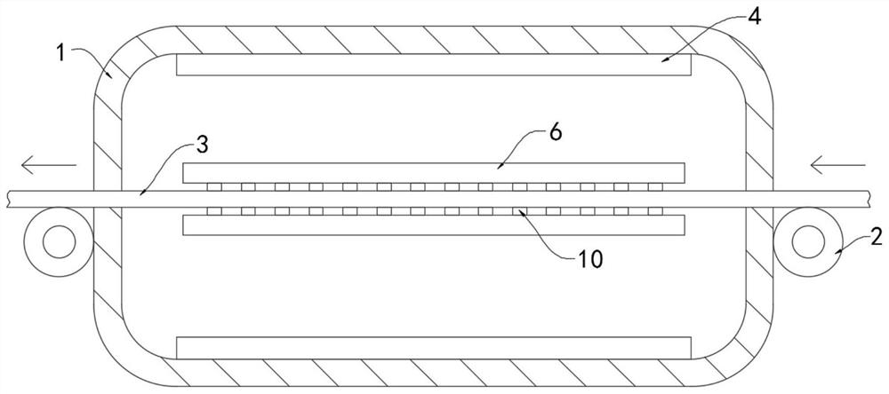
[0028] Such as Figure 1-3 As shown, a textile fabric printing and dyeing method based on the principle of magnetization, the specific printing and dyeing method is as follows:

[0029] S1. Place the fabric 3: pass the fabric 3 through the casing 1 and lay it flat on the two conveying rollers 2;

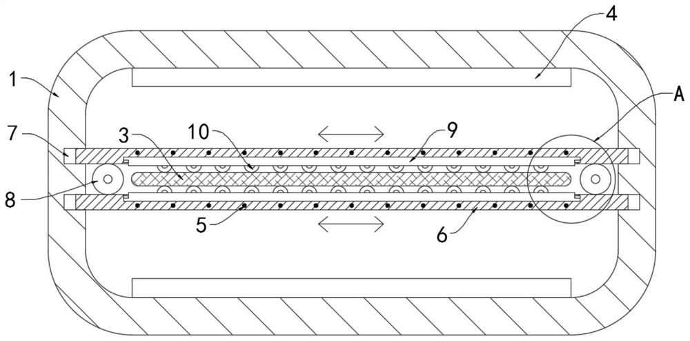
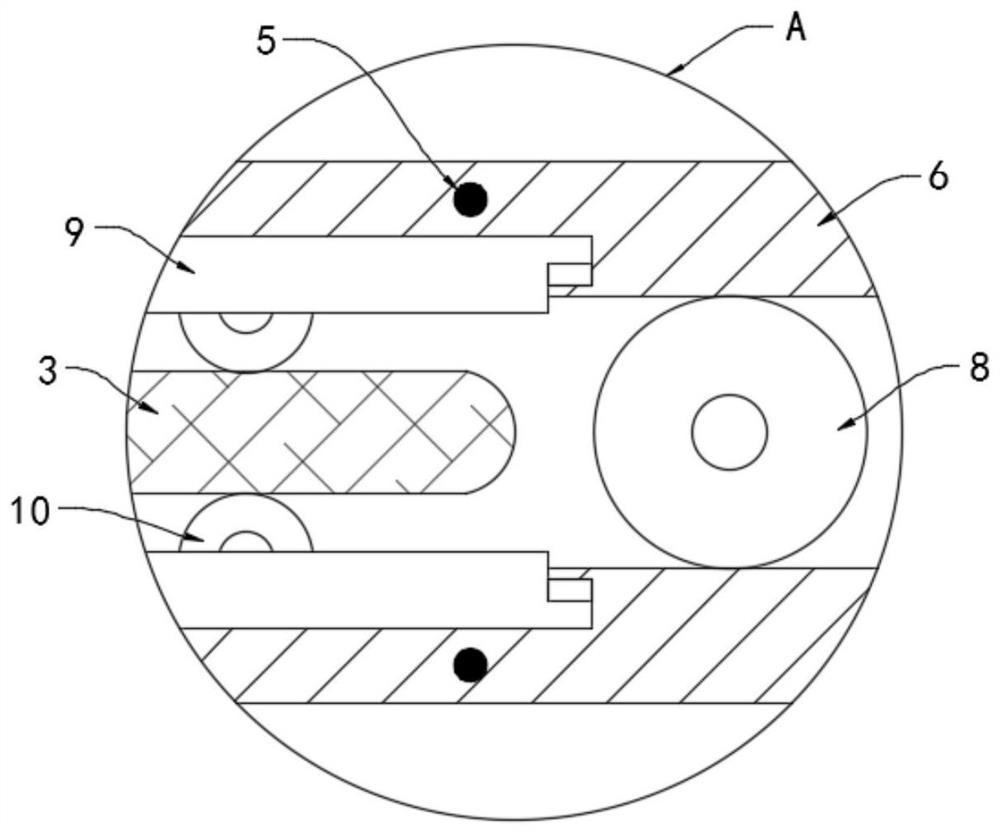
[0030] S2. Rolling the fabric 3: the back and forth rotation of the gear 8 will drive the fixed plate 6 to reciprocate on the fabric 3, thereby driving a plurality of rollers 10 to roll back and forth on the fabric 3, thereby promoting the absorption of the dye solution by the fabric 3;

[0031] S3, magnetized dye solution: the reciprocating movement of the fixed plate 6 drives the wire 5 to cut the magnetic induction line between the two permanent magnet plates 4 to generate current, and the energized extrusion plate 9 will generate magnetism, because the moving directions of the two fixed plates 6 are opposite , the magnetic poles of the two extruded plates 9 are always opposite, ...

Embodiment 2

[0046] Such as Figure 4 As shown, the difference between this embodiment and Embodiment 1 is that a sealing bucket 11 is fixedly connected to the connection between the housing 1 and the outlet end of the cloth 3 (such as Figure 4 shown).

[0047] In this embodiment, the sealing bucket 11 is arranged inside the connection between the casing 1 and the outlet end of the cloth 3 and is arranged close to the cloth 3, so that the excess dye on the cloth 3 can be squeezed out when the cloth 3 is conveyed to the outside of the casing 1. Pressing it into the housing 1 can effectively avoid the waste of dye.


PUM


Abstract

The invention belongs to the field of textile, in particular to a textile printing and dyeing method based on a magnetization principle. In the printing and dyeing process, a printing and dyeing device is further included, the printing and dyeing device comprises a shell internally containing dyeing liquid, conveying rollers are arranged on the two ends of the shell, cloth penetrating the whole shell is jointly conveyed on the conveying rollers, two permanent magnet plates with different magnetisms are fixedly connected to the inner top face and the inner bottom face of the shell correspondingly, two fixed plates which are horizontally mounted are arranged in the shell, multiple wires are fixedly embedded in the fixed plates, the two fixed plates are arranged on the upper end and the lowerend of the cloth correspondingly, the two ends of the fixed plates extend to the interior of the shell, sliding grooves matched with the fixed plates are formed in the inner side wall of the shell, aseal hopper is arranged, the seal hopper is arranged in the connecting position of the shell and the cloth outlet end, and is tightly attached to the cloth, in the process of conveying the cloth to the outside of the shell, remaining dye on the cloth is extruded into the shell, and waste of the dye can be effectively avoided.

Description

technical field [0001] The invention belongs to the field of textiles, and in particular relates to a method for printing and dyeing textile fabrics based on the principle of magnetization. Background technique [0002] According to the weaving method, fabrics are divided into two types: weft-knitted fabrics and warp-knitted fabrics. Weft-knitted fabrics are often made of low-elastic polyester yarns or special-shaped polyester yarns, nylon yarns, cotton yarns, wool yarns, etc. Needle knitting, rib plain knitting, double rib jersey knitting, jacquard knitting and terry knitting, etc., are woven on various weft knitting machines. [0003] In the processing of textile fabrics, it is often necessary to print and dye the fabrics. Most of the traditional printing and dyeing devices use high temperature to cook and stir the fabrics inside to make the dyes adhere to the fabrics, which not only easily causes more wrinkles in the fabrics, but also Placing them in agglomerates in the ...

Claims


Application Information

Patent Timeline
Patent Type & Authority Applications(China)
IPC IPC(8): D06B19/00D06B23/20
CPCD06B19/00D06B23/20
Inventor 谭秀娇陈豪
Owner 谭秀娇
Why Eureka
Try Eureka