Self-anchored suspension bridge bearing bottom sliding support device and longitudinal displacement adjustment method

A technology for self-anchored suspension bridges and supporting devices, which is applied to bridges, bridge construction, bridge parts, etc., can solve the problems of affecting the normal working state of bearings, expensive large bearings, and damage to bearings, and achieves easy adjustment methods operation, improving the stress condition of longitudinal shear deformation, and prolonging the service life

Inactive Publication Date: 2020-11-03
CHANGAN UNIV
View PDF7 Cites 0 Cited by
  • Summary
  • Abstract
  • Description
  • Claims
  • Application Information

AI Technical Summary

Problems solved by technology

Different from the ground-anchored suspension bridge, the main cable of the self-anchored suspension bridge is anchored on the main girder to form a longitudinal self-balancing system. As a result, there is a problem that cannot be ignored in the bearings of self-anchored suspension bridges. After the construction of the whole bridge is completed, the main girder itself will need to overcome the horizontal component force of the main cable. The upper and lower seat plates of the bridge are respectively connected with the bottom of the bridge and the top of the abutment, thus driving the support to produce longitudinal shear deformation, which will cause serious damage to the support in the long run and affect the normal working state of the support
The current solution to this problem is limited to replacing the support, but the process of replacing the support is complicated and the cost of replacing a large support is expensive, and the economy is poor

Method used


Image

  • Self-anchored suspension bridge bearing bottom sliding support device and longitudinal displacement adjustment method
  • Self-anchored suspension bridge bearing bottom sliding support device and longitudinal displacement adjustment method
  • Self-anchored suspension bridge bearing bottom sliding support device and longitudinal displacement adjustment method

Examples


Embodiment Construction

[0027] The present invention will be described in further detail below in conjunction with the accompanying drawings.

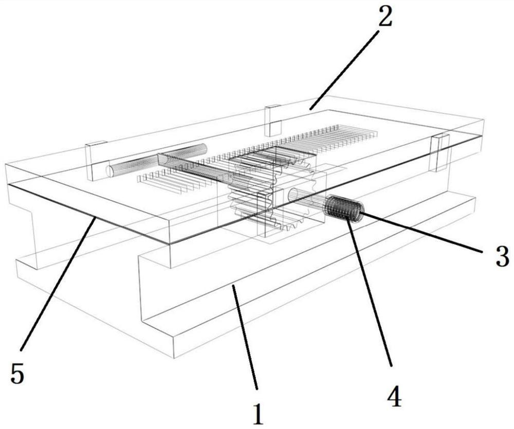
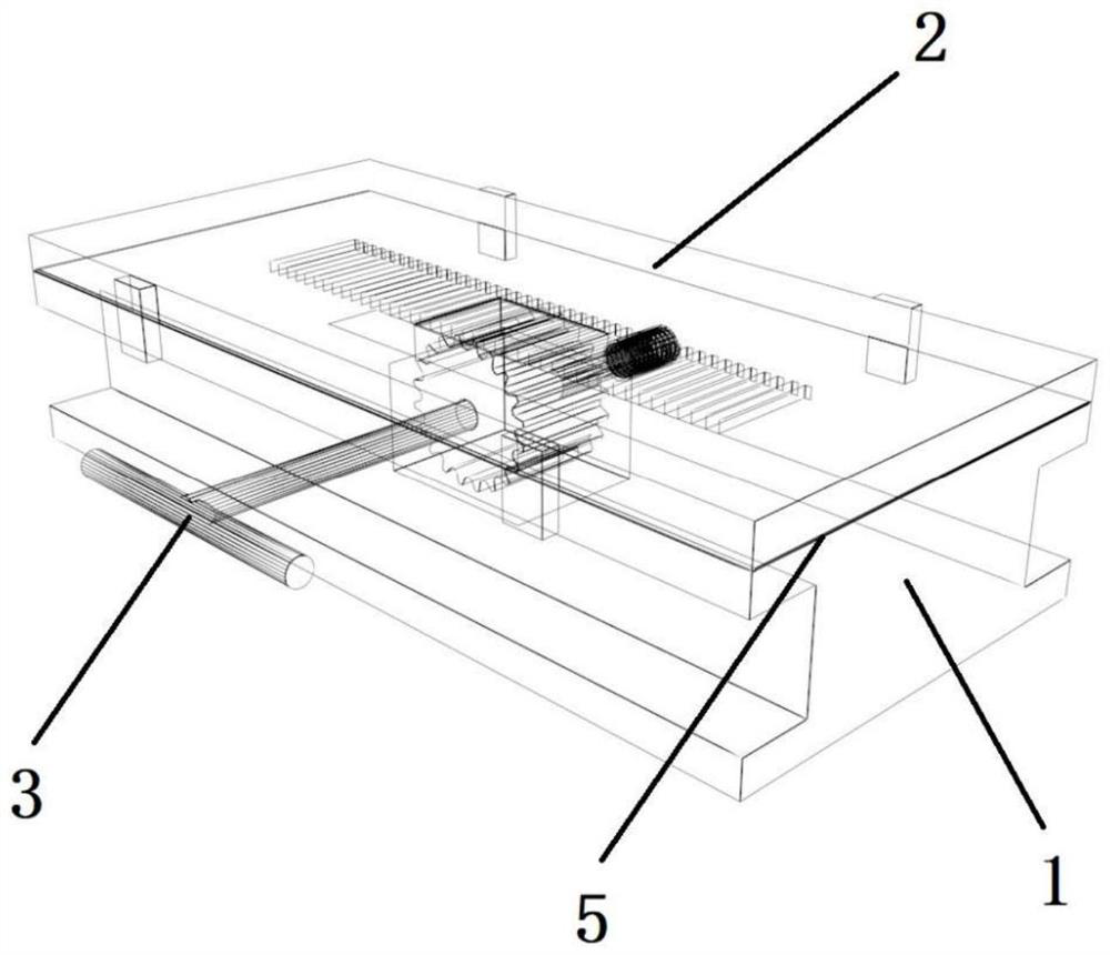
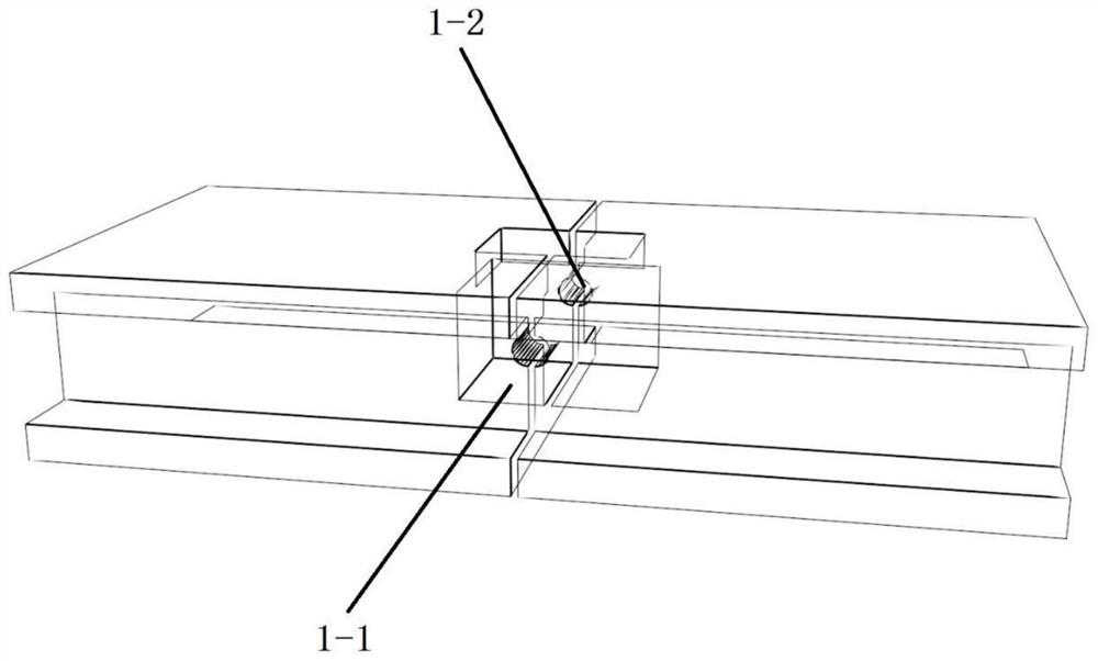
[0028] see Figure 1-2 , The self-anchored suspension bridge bearing bottom sliding support device of the present invention structurally includes a support guide rail 1, a sliding plate 2, a transmission spur gear shaft 3, a fixed nut 4, a sliding washer 5 and a temporary jack. Such as image 3 As shown, the sliding plate 2 is installed on the supporting guide rail 1, and the supporting guide rail 1 is provided with a cavity 1-1, and the two sides of the cavity 1-1 communicate with the hole 1-2 that runs through the supporting guide rail 1 transversely, and the supporting guide rail 1 is composed of It is assembled from two parts separated longitudinally from the cavity 1-1. see Figure 4 , the lower surface of the sliding plate 2 is processed with equally spaced grooves 2-2, and the two sides of the sliding plate 2 are symmetrically provided with four lim...


PUM


Abstract

A Bottom-sliding support device of a self-anchored suspension bridge support and a longitudinal displacement adjusting method are disclosed. The sliding support device comprises a sliding plate mounted on a support guide rail. A lower surface of the sliding plate is machined with equispaced grooves, which are transmitted through a transmission spur gear shaft arranged on the support guide rail andan equispaced groove of the sliding plate. The top of the sliding plate is fixedly connected with the lower seat plate of the support of the curved inclined bridge. The transmission spur gear shaft comprises a transmission shaft and an intermediate spur gear sleeved on the transmission shaft. The tail end of the transmission shaft is processed with threads and fixed nuts are installed. When the fixed nuts are tightened, the position of the sliding plate can be fixed, and when the transmission shaft is adjusted, the sliding plate can be opened. When the longitudinal displacement is adjusted, one jack is installed on each side of the support guide rail, the jack is started to synchronously jack up to the set safe height, the intermediate spur gear is driven to rotate through the transmission shaft, and the sliding plate drives the lower seat plate of the self-anchored suspension bridge support to carry out longitudinal translation. The invention has the advantages of simple structure, easy operation and high precision.

Description

technical field [0001] The invention belongs to the field of road and bridge construction, and in particular relates to a sliding support device at the bottom of a self-anchored suspension bridge support and a method for adjusting longitudinal displacement, which can improve the longitudinal shear deformation of the self-anchored suspension bridge support due to beam compression. Background technique [0002] Self-anchored suspension bridges are more and more popular in the engineering field because of their beautiful shape and strong adaptability to terrain and geology, especially in urban small-span bridges. It is a very competitive solution. Different from the ground-anchored suspension bridge, the main cable of the self-anchored suspension bridge is anchored on the main girder to form a longitudinal self-balancing system. As a result, there is a problem that cannot be ignored in the bearings of self-anchored suspension bridges. After the construction of the whole bridge ...

Claims


Application Information

Patent Timeline
Patent Type & Authority Patents(China)
IPC IPC(8): E01D19/04E01D21/00
CPCE01D19/04E01D19/048E01D21/00
Inventor 王晓明白云腾邓耀张常权徐腾杨帆王旭东阳威
Owner CHANGAN UNIV
Why Eureka
Try Eureka