Underground diaphragm wall grooving method under complicated geological conditions

A technology of complex geological conditions and underground diaphragm wall, applied in the direction of earth mover/shovel, construction, etc., can solve the problems of high construction cost and low trough forming efficiency, so as to reduce the trough construction cost and shorten the trough forming time. , Improve the effect of slotting efficiency

Inactive Publication Date: 2019-01-04
CHINA RAILWAY NO 2 ENG GRP CO LTD +1
View PDF5 Cites 6 Cited by
  • Summary
  • Abstract
  • Description
  • Claims
  • Application Information

AI Technical Summary

Problems solved by technology

[0007] The object of the present invention is to provide an underground diaphragm wall under complex geological conditions for the problems of low trenching efficiency and high construction cost in the three trenching methods currently used when constructing underground diaphragm walls under complex geological conditions. Diaphragm wall trough forming method. This trough forming method combines the advantages and disadvantages of the above three trough forming methods. In the actual trough forming construction, cross operation is adopted to give full play to the advantages of each method, which is conducive to improving the trough forming efficiency and reducing the Trough construction cost

Method used


Image

  • Underground diaphragm wall grooving method under complicated geological conditions
  • Underground diaphragm wall grooving method under complicated geological conditions
  • Underground diaphragm wall grooving method under complicated geological conditions

Examples


Embodiment

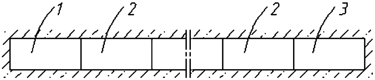
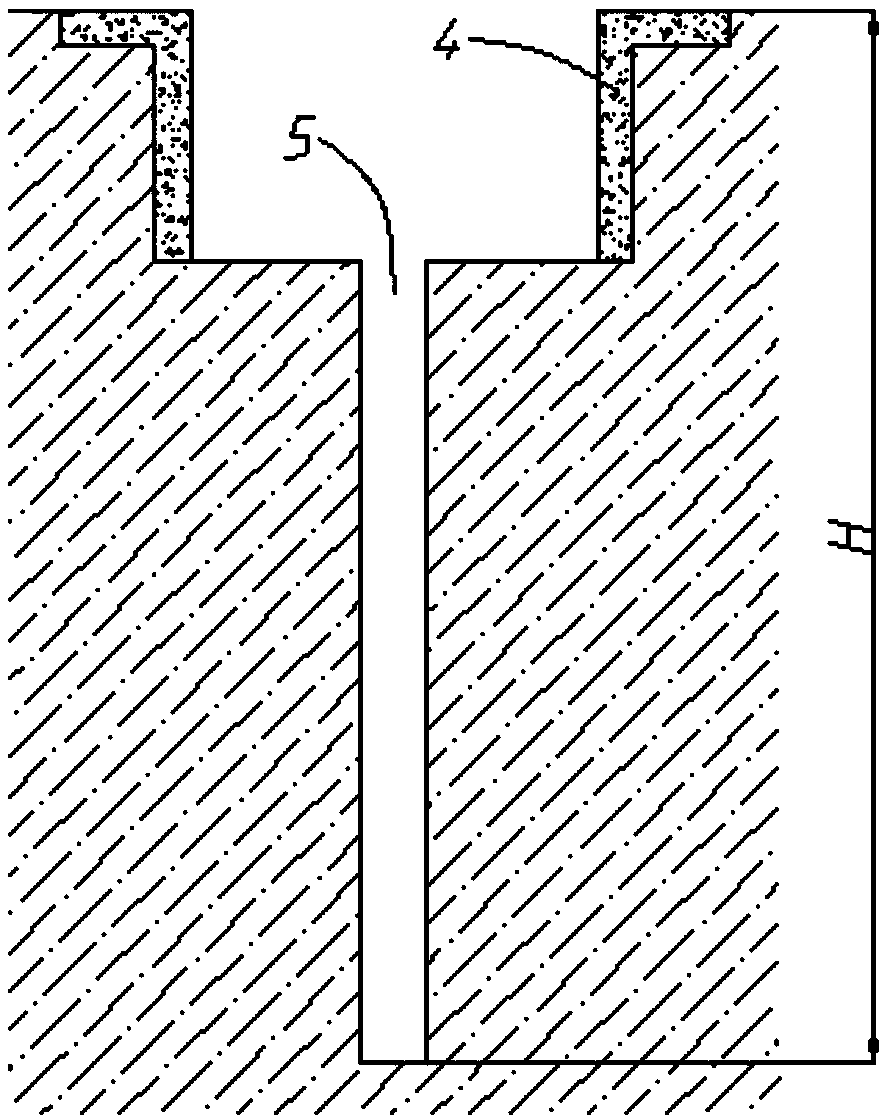
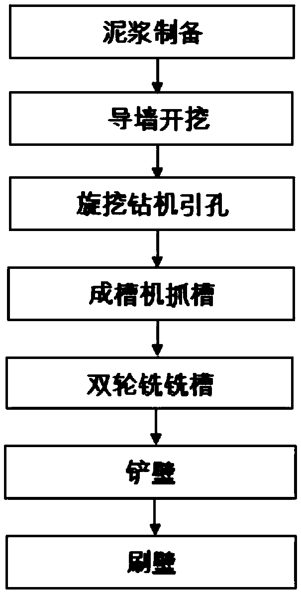
[0032] Such as Figure 1-Figure 3 As shown, the underground diaphragm wall forming groove method under complex geological conditions in this implementation includes the following steps:

[0033] a. Use a rotary drilling rig to guide the hole, and the hole depth is the same as the depth of the underground diaphragm wall groove;

[0034] b. After the lead hole is completed, use the groove forming machine to grasp the groove, and judge the construction depth and the stratum;

[0035] c. When the construction depth reaches the medium-weathered or slightly-weathered rock formation, use double-wheel milling for grooving construction.

[0036] The present invention uses a rotary drilling rig to introduce the hole to form the free surface of the groove section, which reduces the difficulty of construction and facilitates subsequent construction. During the hole introduction process, the stratum distribution of the groove section can also be clarified; after the hole introduction is c...


PUM


Abstract

The invention relates to the field of construction, in particular to an underground diaphragm wall grooving method under complicated geological conditions. The method comprises the following steps: (1) a rotary drilling rig is used for leading holes; and the holes are as deep as underground diaphragm wall grooves; (2) after hole leading, a grooving machine is used for grabbing the grooves, and a stratum of the construction depth is judged; and (3) when the construction depth reaches an intermediary weathered sandstone layer or a weak weathered sandstone layer, the double-wheel milling is usedfor grooving construction. Through hole leading by the rotary drilling rig, groove sections form free faces, so that the construction difficulty is reduced, and the subsequent construction is convenient; the grooving machine is used for grabbing the grooves after hole leading; when the construction depth reaches the intermediary weathered sandstone layer, the double-wheel milling is used for grooving construction; and the grooving method combines respective advantages and defects of three grooving methods in the prior art, adopts the intersecting operation in the actual grooving construction to fully exert the advantages of each method, facilitates improvement of the grooving efficiency, and meanwhile, reduces the grooving construction cost.

Description

technical field [0001] The invention relates to the field of building construction, in particular to a method for forming grooves in an underground continuous wall under complex geological conditions. Background technique [0002] The underground diaphragm wall is a kind of trenching machine used on the ground for basic engineering. Along the peripheral axis of the deep excavation project, a long and narrow deep trench is excavated under the condition of mud retaining wall. After the trench is cleaned, it is hung in the trench Reinforcement cages, and then use the conduit method to pour underwater concrete to form a unit trough section. In this way, a continuous reinforced concrete wall is built underground as a water interception, anti-seepage, load-bearing, and water-retaining structure. [0003] At present, the commonly used underground continuous wall grooving methods in China mainly include hydraulic grab grooving machine, rotary drilling rig combined with double-wheel ...

Claims


Application Information

Patent Timeline
Patent Type & Authority Applications(China)
IPC IPC(8): E02F5/02
CPCE02F5/02
Inventor 尚友磊任瑞城唐维冬万高峰熊静平
Owner CHINA RAILWAY NO 2 ENG GRP CO LTD
Why Eureka
Try Eureka