Supercharge Your Innovation With Domain-Expert AI Agents!

Control method and system for vehicle particulate filter

A particle trap and control method technology, which is applied in the control field of vehicle particle traps, can solve problems such as unreasonable regeneration of particle traps, and achieve the goal of improving PM/PN emissions and reducing PM/PN emissions Effect

Active Publication Date: 2020-12-11
UNITED AUTOMOTIVE ELECTRONICS SYST
View PDF5 Cites 0 Cited by
  • Summary
  • Abstract
  • Description
  • Claims
  • Application Information

AI Technical Summary

Problems solved by technology

[0005] The purpose of the present invention is to provide a control method and system for vehicle particulate traps to solve the problem of unreasonable regeneration of existing vehicle particulate traps

Method used


Image

  • Control method and system for vehicle particulate filter
  • Control method and system for vehicle particulate filter
  • Control method and system for vehicle particulate filter

Examples


Embodiment 1

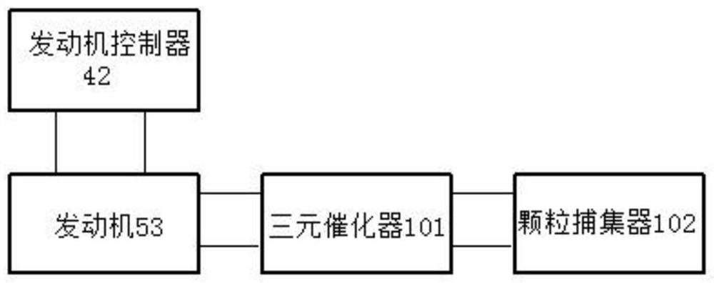
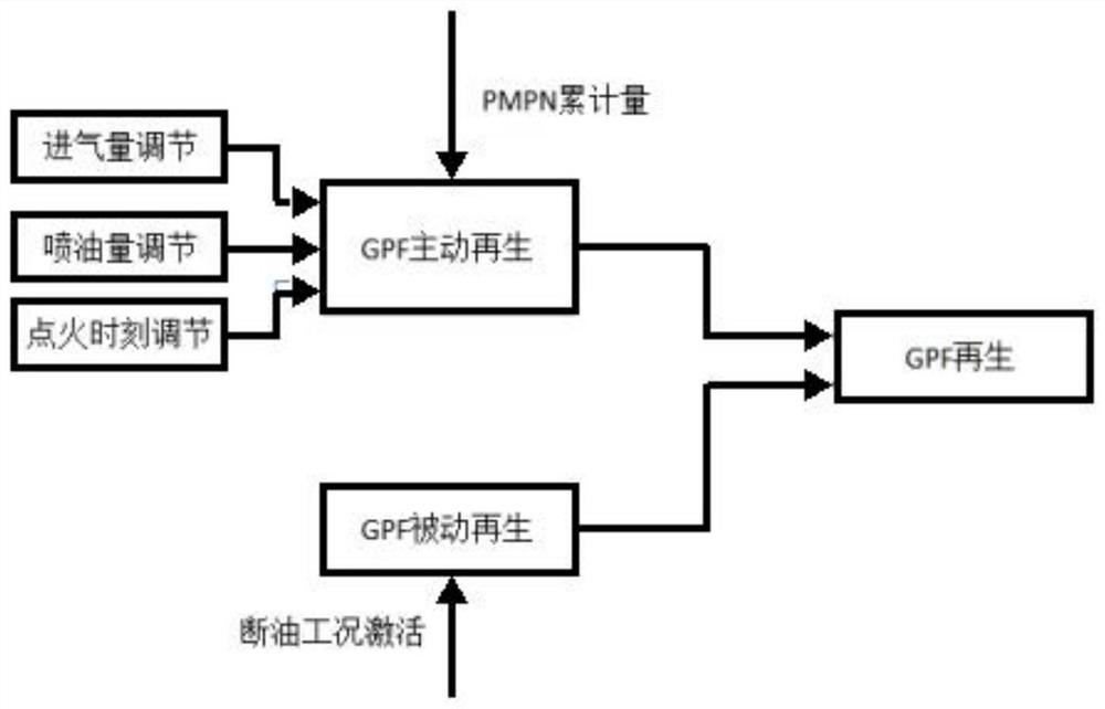
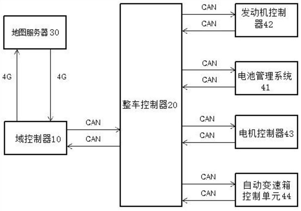
[0052] This embodiment provides a control method for a vehicle particle trap, such as Figure 3-4 As shown, the control method of the vehicle particle trap includes: when the vehicle is ready to run, the domain controller 10 inputs the starting point and destination location information to the map server 30, and the map server 30 according to the starting point and destination location information The information is calculated to obtain the map information in front of the vehicle; the domain controller 10 obtains the map information in front of the vehicle from the map server 30, and combines the vehicle sensor information to generate road condition information between the starting point and the destination; The vehicle controller 20 sends hybrid power system status information to the domain controller 10; the domain controller 10 combines the road condition information between the starting point and the destination and the hybrid power system status information to obtain the s...

Embodiment 2

[0061] This embodiment also provides a control system for a vehicle particulate trap, such as Figure 3-4 As shown, the control system of the vehicle particle trap includes a map server 30, a domain controller 10 and a vehicle controller 20, wherein: when the vehicle is ready to run, the domain controller 10 inputs to the map server 30 Starting point and destination location information, the map server 30 calculates the map information in front of the vehicle according to the starting point and destination location information; the domain controller 10 obtains the map in front of the vehicle from the map server 30 information, combined with vehicle sensor information, to generate road condition information between the starting point and the destination; the vehicle controller 20 sends hybrid system status information to the domain controller 10; the domain controller 10 combines the starting point Road condition information between the starting point and the destination and th...


PUM


Abstract

The invention provides a control method and system of a vehicle particle trap. The control method comprises the following steps that when a vehicle is ready to run, position information of a startingpoint and a destination is input to a map server through a domain controller, and map information in front of the vehicle is calculated through the map server according to the position information ofthe starting point and the destination; the map information in front of the vehicle is obtained from the map server through the domain controller, and combined with vehicle sensor information, trafficinformation between the starting point and the destination is generated; state information of a hybrid power system is sent to the domain controller through a whole vehicle controller; the traffic information between the starting point and the destination and the state information of the hybrid power system are combined through the domain controller to obtain a PM / PN prediction emission curve between the starting point and the destination;an active regeneration and passive regeneration allocation strategy of the particle trap is calculated and obtained through the domain controller accordingto the PM / PN prediction emission curve between the starting point and the destination; and the active regeneration and passive regeneration allocation strategy of the particle trap is sent to the whole vehicle controller through the domain controller.

Description

technical field [0001] The invention relates to the technical field of vehicle control, in particular to a control method and system for a vehicle particle trap. Background technique [0002] Gasoline engine particulate filter (GPF) is a particulate matter trapping device for gasoline engines. Its basic principle is to capture the particulate matter in the exhaust gas when the exhaust gas passes through a labyrinth carrier. The trapping efficiency can reach 60-90%, so the GPF can be improved The robustness of particulate matter emissions, while the GPF is coated, has a certain ability to convert gaseous emissions, which can reduce gas emissions. [0003] figure 1 It is a structural diagram of an engine and an aftertreatment system of a conventional gasoline vehicle, and the system includes an engine 53, an engine controller 42 (EMS), a three-way catalytic converter 101 (TWC), and a particulate filter 102 (GPF). Among them, TWC can convert the gaseous harmful emissions prod...

Claims


Application Information

Patent Timeline
IPC IPC(8): F01N9/00F02D41/02F02D41/30F02P5/15B60W20/12B60W20/16B60W10/06B60W10/08
CPCB60W10/06B60W10/08B60W2710/0666B60W2710/083B60W20/12B60W20/16F01N9/002F02D41/0002F02D41/029F02D41/30F02D2200/1002F02D2200/101F02P5/1504Y02T10/40Y02T10/62
Inventor 宋福祥张松刘军陈宇清刘佳熙王国祥王景
Owner UNITED AUTOMOTIVE ELECTRONICS SYST
Features
  • R&D
  • Intellectual Property
  • Life Sciences
  • Materials
  • Tech Scout
  • Unparalleled Data Quality
  • Higher Quality Content
  • 60% Fewer Hallucinations
Learn More