Aviation engine labyrinth seal structure with tapered leading air holes

A technology of aero-engines and air-inducing holes, which is applied in the direction of engine components, machines/engines, gas turbine devices, etc., can solve the problems of improving the sealing effect, and achieve the effects of reducing leakage, reducing leakage, and increasing circumferential flow damping

Pending Publication Date: 2019-01-04
CHINA HANGFA CHANGZHOU LANXIANG MACHINERY CO LTD
View PDF0 Cites 10 Cited by
  • Summary
  • Abstract
  • Description
  • Claims
  • Application Information

AI Technical Summary

Problems solved by technology

However, when the number of teeth and the sealing gap are fixed, it is not easy to significantly improve the sealing effect by simply changing the rest of the structural parameters of the grate teeth.

Method used


Image

  • Aviation engine labyrinth seal structure with tapered leading air holes
  • Aviation engine labyrinth seal structure with tapered leading air holes
  • Aviation engine labyrinth seal structure with tapered leading air holes

Examples


Embodiment 1

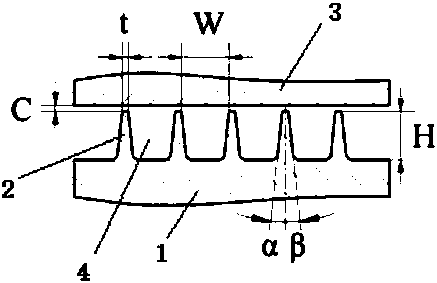
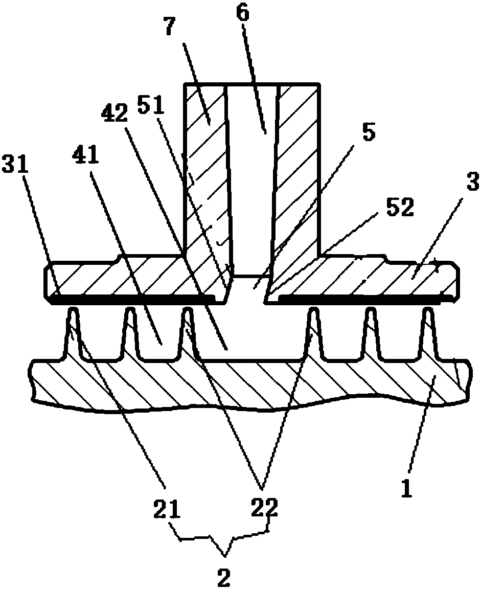
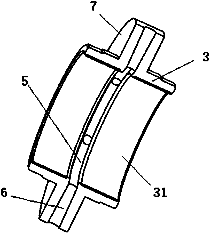
[0019] Example 1 as Figure 2 to Figure 4 As shown, the aero-engine grate seal structure with tapering air-introduction holes in this embodiment includes a rotating shaft 1 and a grate bushing ring 3. The rotating shaft 1 is provided with 6 sections of grate teeth 2, and the first one of them is arranged according to the flow direction of the airflow. The 1st, 2nd, 5th, and 6th grate teeth are the end grate teeth 21, and the 3rd and 4th grate teeth are the central grate teeth 22; Strict clearance C is not more than 0.5mm, between the 1st section and the 2nd section, between the 2nd section and the 3rd section, between the 4th section and the 5th section, The tooth distance W between the 5th section and the 6th section is the same to form a vortex cavity 41 of the same size; the tooth distance between the 3rd section and the 4th section is the 5th section 2.15 times of the tooth pitch between the teeth and the 6th section grate teeth, so that a wider central bleed air tooth ch...


PUM


Abstract

The invention relates to an aviation engine labyrinth seal structure with tapered leading air holes, which comprises a rotating shaft provided with a plurality of labyrinths, a labyrinth bushing ring,wherein an annular groove is arranged in the inner wall of the labyrinth bushing ring in the circumferential direction; the annular groove comprises an air inlet side wall, an air outlet side wall and an annular bottom wall, the air inlet side wall is obliquely arranged so that the connection part of the air inlet side wall and the inner wall of the labyrinth bushing ring is diffused in a horn shape to guide the leakage airflow flowing along the inner wall of the labyrinth bushing ring; the annular bottom wall is provided with a plurality of tapered leading air holes for introducing air flowalong the radial direction of the labyrinth bushing ring, the tapered leading holes are arranged in a conical shape, and the diameter of an air outlet end of the tapered leading holes is smaller thanthe diameter of an air inlet end so as to pressurize the air flow introduced into the annular groove; When assembled, the air inlet side wall and air outlet side wall of the annular groove are arranged in the same labyrinth cavity, and when the leakage air flow flows to the annular groove, the air flow enters the annular groove from the inlet side wall.

Description

technical field [0001] The invention relates to the technical field of aero-engines, in particular to an aero-engine grate sealing structure with tapered bleed holes. Background technique [0002] From the birth of the aviation gas turbine engine to the rapid development today, gas sealing has always been one of the important issues. The grate tooth seal is the most widely used gas seal structure in active aero-engines, and is mainly used for oil and gas isolation of the lubricating oil sealing system between compressor stages, turbine stages, blade tops and bearing cavities. Low fuel consumption, high thrust-to-weight ratio, high reliability and durability are the development directions of aero-engines, but the increase in engine pressure ratio and internal temperature increases the leakage of the internal flow system, so the grate sealing system directly affects the aero-engine. Fuel consumption, reliability and durability. [0003] Research at home and abroad shows that...

Claims


Application Information

Patent Timeline
Patent Type & Authority Applications(China)
IPC IPC(8): F02C7/28F01D11/06
CPCF02C7/28F01D11/06
Inventor 李文凯武威
Owner CHINA HANGFA CHANGZHOU LANXIANG MACHINERY CO LTD
Why Eureka
Try Eureka