Energy-saving indoor air exchange system and method

A technology for indoor air and exchange systems, applied in the field of ventilation systems, can solve the problems of not being able to achieve the purpose of energy saving, and not comprehensively considering the energy consumption of heat exchangers and the energy-saving effect of fresh air.

Active Publication Date: 2019-01-04
SHANGHAI CONSTRUCTION GROUP
View PDF8 Cites 4 Cited by
  • Summary
  • Abstract
  • Description
  • Claims
  • Application Information

AI Technical Summary

Problems solved by technology

[0005] Aiming at the problem that the current air-conditioning system does not comprehensively consider the overall energy-saving effect between the energy consumption of the heat exchanger and the energy-saving of fresh air, and cannot achie

Method used


Image

  • Energy-saving indoor air exchange system and method
  • Energy-saving indoor air exchange system and method
  • Energy-saving indoor air exchange system and method

Examples


Example Embodiment

[0031] Example one

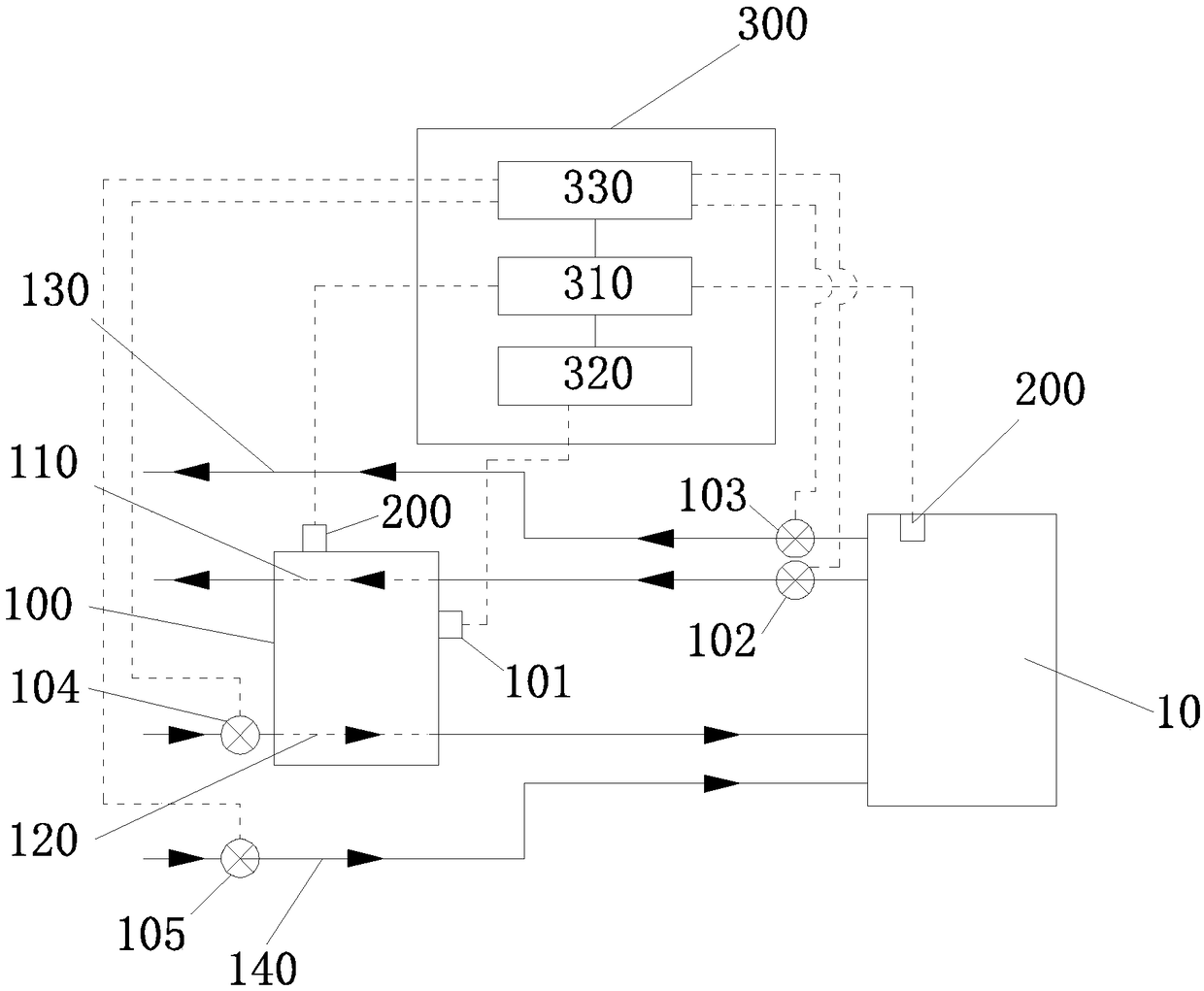
[0032] Such as figure 1 As shown, the energy-saving indoor air exchange system provided by this embodiment includes a heat exchanger 100, a temperature sensor 200, and a controller 300.

[0033] Wherein, the heat exchanger 100 is provided with an exhaust air duct 110 and a fresh air duct 120 capable of performing heat exchange, and an exhaust air bypass duct 130 and a fresh air bypass duct that do not participate in heat exchange are also provided inside or outside the heat exchanger 100. 140; the inlets of the exhaust air pipe 110, the exhaust air bypass pipe 130, the fresh air pipe 120, and the fresh air bypass pipe 140 are respectively provided with valve one 102, valve two 103, and valve which are connected to the valve control unit 330 in the controller 300 Three 104, valve four 105. The heat exchanger 100 also includes an on-off switch 101 connected to the switch control unit 320 in the controller 300.

[0034] Among them, the temperature sensor 200 is us...

Example Embodiment

[0042] Example two

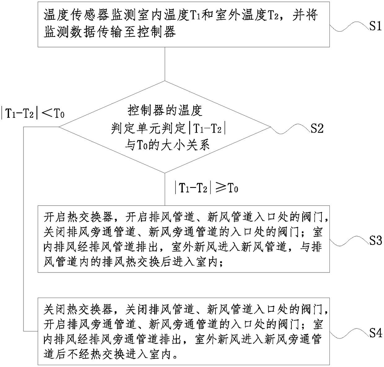
[0043] Such as image 3 As shown, this embodiment provides a method for air exchange using the energy-saving indoor air exchange system in the first embodiment, which will be combined with Figure 1 to Figure 3 This method is further introduced. The method includes the following steps:

[0044] S1. Temperature sensor 200 monitors indoor temperature T 1 And outdoor temperature T 2 , And transmit the monitoring data to the controller 300;

[0045] S2. The temperature determination unit 310 of the controller 300 compares |T 1 -T 2 |With T 0 Size when |T 1 -T 2 |≥T 0 When, go to step S3; when |T 1 -T 2 |0 When, go to step S4;

[0046] S3. Open the heat exchanger 100, open the exhaust pipe 110, the valves at the inlet of the fresh air pipe 120, and close the valves at the inlet of the exhaust bypass pipe 130 and the fresh air bypass pipe 140; indoor exhaust air is discharged through the exhaust pipe 110 , The outdoor fresh air enters the fresh air duct 120, and enter...


PUM


Abstract

The invention discloses an energy-saving indoor air exchange system and method. The air exchange system comprises a heat exchanger, a temperature sensor and a controller; an exhaust pipe and a fresh air pipe capable of exchanging heat are arranged in the heat exchanger; an exhaust bypass pipe and a fresh air bypass pipe are provided; the temperature sensor is used for monitoring an indoor temperature T1 and an outdoor temperature T2; the controller comprises a temperature judging unit, a switch control unit and a valve control unit; the temperature judging unit compares an absolute value of T1minus T2 with T0; and according to the comparing result, the switch control unit controls startup and stop of the heat exchanger, and the valve control unit controls opening and closing of a valve. The method can automatically judge the indoor and outdoor temperature difference, and automatically controls the startup and stop of the heat exchanger, an exhaust path and a fresh path, so that an airconditioning system and the heat exchanger are totally located in an energy saving state after the heat exchanger is started, and the advantages of energy conservation and automatic adjustment are achieved.

Description

Technical field [0001] The invention relates to an energy-saving indoor air exchange system and method, and belongs to the technical field of ventilation systems. Background technique [0002] We know that air-conditioned rooms are often relatively closed spaces. When people are densely populated, the air quality will deteriorate, causing harm to the human body. Therefore, existing air conditioning systems are often provided with fresh air channels and exhaust air channels to exhaust part of the indoor air and at the same time introduce outdoor air to improve indoor air quality. [0003] Due to the temperature difference between the air in the air-conditioned room and the outdoor air, it will increase the load of the air-conditioning system. The load of fresh air will often account for 30%-50% of the load of the entire air-conditioning system. Especially in the area of ​​densely populated buildings in summer, the load of fresh air may even account for More than 70%, so reducing th...

Claims


Application Information

Patent Timeline
IPC IPC(8): F24F7/08F24F13/30F24F11/89F24F11/64F24F11/84F24F11/47F24F110/10F24F110/12
CPCF24F7/08F24F13/30F24F11/47F24F11/64F24F11/84F24F11/89F24F2110/10F24F2110/12
Inventor 沈丹丹黄玉林贾珍刘平杜晓燕
Owner SHANGHAI CONSTRUCTION GROUP
Why Eureka
Try Eureka