Main beam welding clamp tool

A technology of welding fixtures and tooling, which is applied in welding equipment, auxiliary welding equipment, welding/cutting auxiliary equipment, etc., and can solve problems such as inability to accurately position components

Active Publication Date: 2019-01-08
浙江摩科机器人科技有限公司
View PDF4 Cites 5 Cited by
  • Summary
  • Abstract
  • Description
  • Claims
  • Application Information

AI Technical Summary

Problems solved by technology

The welding robot is equipped with welding tongs or welding (cutting) guns on the flange of the final axis of the industrial robot, so that it can be welded, cut or thermally sprayed. When welding components for large main beams such as solar power poles, The positi

Method used


Image

  • Main beam welding clamp tool
  • Main beam welding clamp tool
  • Main beam welding clamp tool

Examples


Embodiment Construction

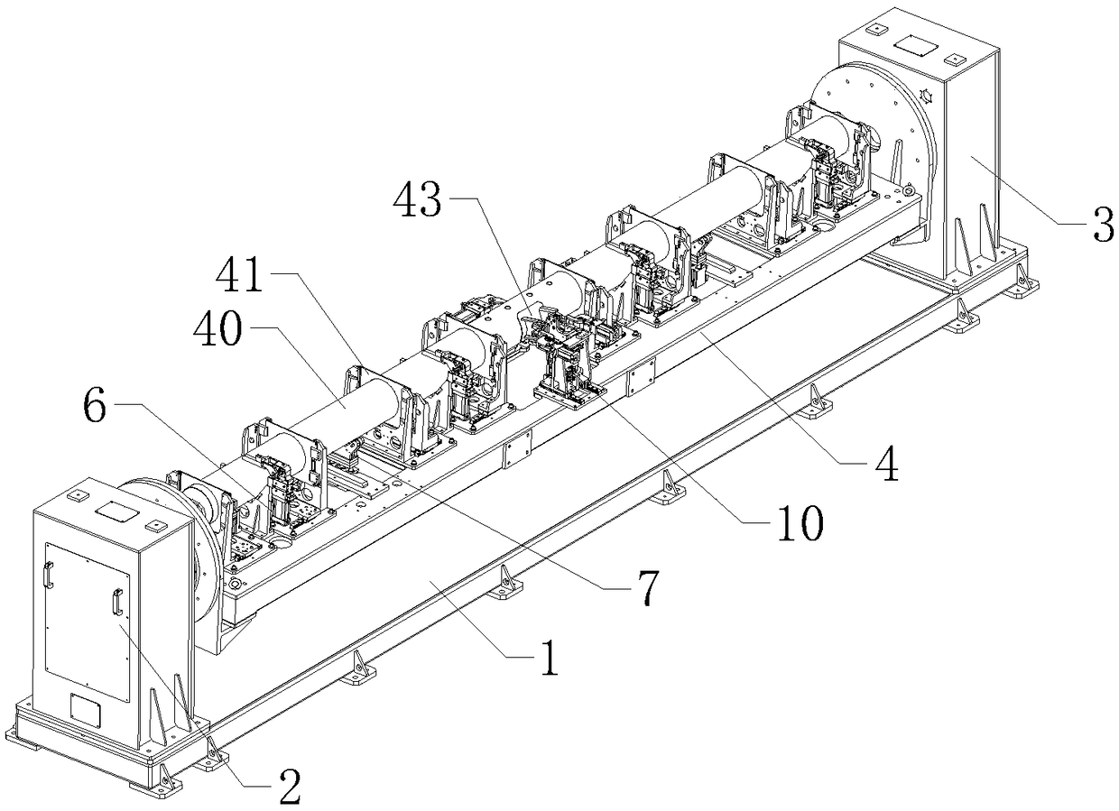
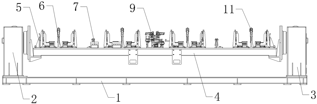
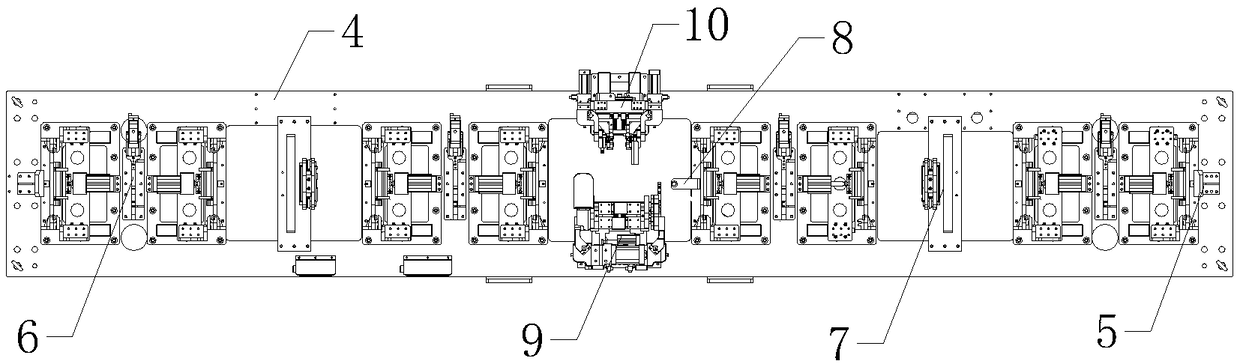
[0027] Below in conjunction with accompanying drawing and embodiment of description, specific embodiment of the present invention is described in further detail:

[0028] refer to Figure 1 to Figure 12The main girder welding jig shown includes base 1, active positioner 2, driven positioner 3 and clamping and fixing components, base 1 is set horizontally, active positioner 2 and driven positioner 3 They are vertically arranged at both ends of the top of the base 1, and the clamping and fixing components include a support plate 4, two main beam end face limit mechanisms 5 and four support beam positioning clamping mechanisms 6 arranged on the top of the support plate 4. , two main beam support mechanisms 7 structures, a main beam positioning pin 8, a main beam support fixture 9 and a push rod support fixture 10, the support plate 4 is a rectangular structure arranged horizontally and its two ends are respectively connected to the active variable The positioner 2 and the driven...


PUM


Abstract

The invention relates to the field of welding clamps, in particular to a main beam welding clamp tool. The main beam welding clamp tool comprises a base, a drive positioner, a driven positioner and aclamping fixing assembly, wherein the clamping fixing assembly comprises a bearing plate, two main beam end surface limiting mechanisms which are arranged on the top of the bearing plate, four supporting beam positioning clamping mechanisms, two main beam supporting mechanisms, a main beam dowel pin, a main beam supporting base clamp and a pushing rod supporting base clamp; the bearing plate is ofa horizontally arranged rectangular structure, and the two ends of the bearing plate are fixedly connected with the drive positioner and the driven positioner separately; the main beam supporting base clamp and the pushing rod supporting base clamp are positioned on the middle position of the bearing plate; and each supporting beam positioning clamping mechanism comprises a first pressing air cylinder which can press a main beam from the above. The main beam welding clamp tool can precisely and stably fix the main beam and a welding component thereof, so that a welding robot automatically welds.

Description

technical field [0001] The invention relates to the field of welding fixtures, in particular to a main beam welding fixture tooling. Background technique [0002] A welding robot is an industrial robot engaged in welding (including cutting and spraying). According to the definition of a standard welding robot by the International Organization for Standardization, an industrial robot is a multi-purpose, reprogrammable automatic control operation machine with three or More programmable axes for use in industrial automation. In order to adapt to different purposes, the mechanical interface of the last axis of the robot is usually a connecting flange, which can be connected to different tools or end effectors. The welding robot is equipped with welding tongs or welding (cutting) guns on the flange of the final axis of the industrial robot, so that it can be welded, cut or thermally sprayed. When welding components for large main beams such as solar power poles, The position of...

Claims


Application Information

Patent Timeline
IPC IPC(8): B23K37/047B23K37/04
CPCB23K37/0443B23K37/047
Inventor 宋星亮
Owner 浙江摩科机器人科技有限公司
Why Eureka
Try Eureka