Mechanical arm space trajectory tracking dynamic compensation method and system

A trajectory tracking and dynamic compensation technology, applied in manipulators, program-controlled manipulators, manufacturing tools, etc., can solve the problems of complex dynamic models of manipulators, difficult to obtain dynamic models, and unsatisfactory control effects. Less resources, good real-time effect

Active Publication Date: 2019-01-08
BEIJING INST OF RADIO MEASUREMENT
View PDF9 Cites 36 Cited by
  • Summary
  • Abstract
  • Description
  • Claims
  • Application Information

AI Technical Summary

Problems solved by technology

In the prior art, two methods are generally adopted for the space trajectory tracking control of the manipulator: the first method is to directly obtain the target speed from the difference of the joint target angle in the joint control, and feed it to the joint speed controller as the speed feedforward for dynamic control. Compensation, this method is simple to implement but has hysteresis characteristics; the second method is to control according to the dynamic model of the manipulator, but the dynamic model of the six-degree-of-freedom manipulator is complex, and it is difficult to obtain an accurate dynamic model, resulting in control Unsatisfactory effect

Method used


Image

  • Mechanical arm space trajectory tracking dynamic compensation method and system
  • Mechanical arm space trajectory tracking dynamic compensation method and system
  • Mechanical arm space trajectory tracking dynamic compensation method and system

Examples


Embodiment Construction

[0019] In order to make the technical solutions and advantages in the embodiments of the present application clearer, the exemplary embodiments of the present application will be further described in detail below in conjunction with the accompanying drawings. Apparently, the described embodiments are only part of the embodiments of the present application, and Not an exhaustive list of all embodiments. It should be noted that, in the case of no conflict, the embodiments in the present application and the features in the embodiments can be combined with each other.
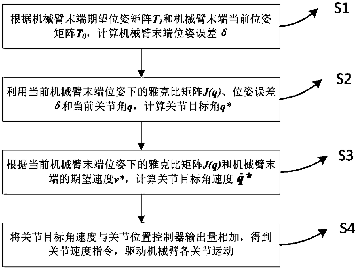
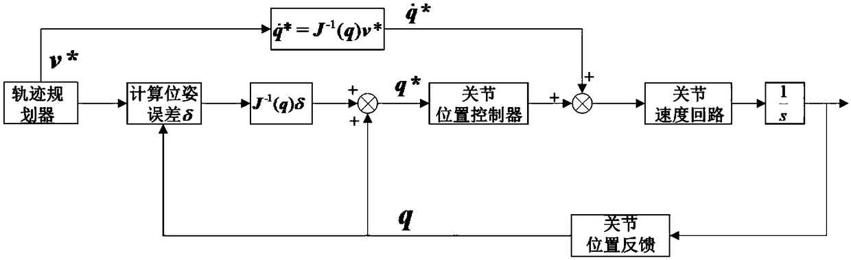
[0020] The core idea of ​​this scheme is to directly obtain the target speed of each joint as the feed-forward amount through the spatial speed output by the terminal trajectory planning, without lag, and with good real-time performance.

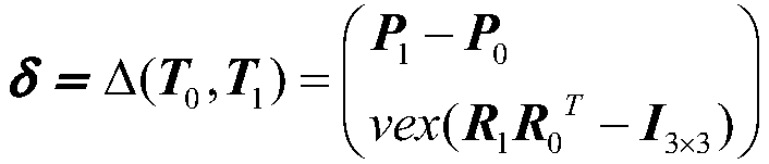
[0021] Such as figure 1 and figure 2 As shown, this solution discloses a dynamic compensation method for space trajectory tracking of a manipulator. This method does not need ...


PUM


Abstract

The invention provides a mechanical arm space trajectory tracking dynamic compensation method and system. The method comprises the following steps: (S1) a terminal pose error delta of a mechanical armis calculated according to a terminal anticipant pose matrix T1 of the mechanical arm and a terminal present pose matrix T0 of the mechanical arm; (S2) a joint target angle q* is calculated by usinga Jacobian matrix J (q), the pose error delta and a present joint angle q under a present terminal pose of the mechanical arm; (S3) a joint target angle speed FORMULA is calculated according to the Jacobian matrix J (q) under the present terminal pose of the mechanical arm and an anticipant speed v* of the terminal of the mechanical arm; and (4) the joint target angle speed FORMULA and an output quantity of a joint position controller are summed to obtain a joint speed instruction to drive each joint of the mechanical arm to move. The method is low in calculating complexity and few in occupiedresource, has no need to consider complicated dynamics models, and is simple, practical and probe to implementation; and each joint target speed is directly obtained through space speed output by terminal trajectory planning as a feedforward quantity without existing hysteresis, so that the instantaneity is achieved.

Description

technical field [0001] The present application relates to the field of space trajectory tracking compensation of a manipulator, in particular to a dynamic compensation method and system for space trajectory tracking of a six-degree-of-freedom manipulator. Background technique [0002] Manipulators, especially six-degree-of-freedom manipulators, have been widely used in industrial production. Manipulator control technology is an important part of the manipulator system, which determines the performance of the manipulator. With the rapid development of modern industry, especially " The proposal of strategies such as "Industry 4.0" and "Made in China 2025" put forward higher requirements for the precision, stability and speed of the robotic arm. [0003] Space trajectory tracking of the manipulator is to realize the movement of the end effector along a given continuous trajectory, and the entire movement trajectory needs to be strictly controlled, and the tracking accuracy of t...

Claims


Application Information

Patent Timeline
Patent Type & Authority Applications(China)
IPC IPC(8): B25J19/00B25J9/16
CPCB25J9/16B25J9/1664B25J19/00
Inventor 韩华涛高景一李竹奇吕泽杉李源耿金鹏吴磊李冬伍魏彦彪
Owner BEIJING INST OF RADIO MEASUREMENT
Why Eureka
Try Eureka