Dynamic wireless charging system based on constant-speed running of vehicle

A wireless charging, fixed-speed technology, applied in electric vehicle charging technology, charging station, vehicle energy storage, etc., can solve the problems of stability and safety cannot be guaranteed, serious energy waste, etc., to ensure stability and energy supply The effect of the sustainability and the avoidance of energy waste

Pending Publication Date: 2019-01-08
GUANGXI POWER GRID ELECTRIC POWER RES INST
View PDF4 Cites 2 Cited by
  • Summary
  • Abstract
  • Description
  • Claims
  • Application Information

AI Technical Summary

Problems solved by technology

As a result, the stability and security of the system cannot be guaranteed, and energy waste is also very serious.

Method used


Image

  • Dynamic wireless charging system based on constant-speed running of vehicle
  • Dynamic wireless charging system based on constant-speed running of vehicle

Examples


Embodiment 1

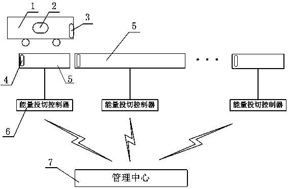
[0020] This embodiment implements a dynamic wireless charging system based on the constant speed of the vehicle, such as figure 1 As shown, the key lies in that an RFID tag 3 and a speed controller 2 are arranged on the body of an electric vehicle 1 with a wireless charging receiving system, and the wireless charging transmission system is set as a wireless charging system for an electric vehicle 1 composed of multiple guide rails 5 . Dedicated channel, the front end of the first section guide rail 5 of described dedicated channel is provided with an RFID reader 4, and described RFID reader 4, constant speed controller 2 are respectively connected with management center 7 by wireless communication; Each section guide rail 5 also An energy switching controller 6 is provided, and the energy switching controller 6 is used to control the energy emission state of the guide rail 5 coil, and is connected with the management center 7 by wireless communication; When the RFID reader 4 r...

Embodiment 2

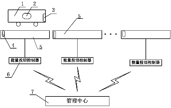
[0030] On the basis of Embodiment 1, the length of each section of guide rail 5 in this embodiment is different, as figure 2 shown. Therefore, in this embodiment, the traveling speed of the electric vehicle 1 is V 2 km / h, there are n sections of guide rails 5 in the dedicated channel, and the length of each section of guide rails 5 is l i (1≤i≤n). The control steps of the energy switching controller 6 in the guide rail 5 by the management center 7 are as follows:

[0031] S1: Calculate the time for electric vehicle 1 to pass through each section of guide rail 5 as

[0032] S2: Record the time point when the electric vehicle 1 enters the dedicated channel, that is, the time point when the RFID reader 4 reads the RFID tag 3 as t 0 , the management center 7 controls the energy switching controller 6 of the i-th guide rail 5 at t i Turn on the wireless energy transmitting coil at all times, where t i = t 0 +t 1 +t 2 +…+t i-1, where 11 = t 0 ;

[0033] S3: The manage...


PUM


Abstract

The invention discloses a dynamic wireless charging system based on constant-speed running of a vehicle. The system is provided with an RFID tag and a constant-speed controller on an electric vehicle,and the wireless charging transmitting system is set as a wireless charging special channel composed of a plurality of guide rails. Wherein, each section of the guide rail is provided with an energyswitching controller for controlling the energy emission state of the guide rail coil; An RFID reader is also provided at the front end of the first section of the guide rail. When the RFID reader reads the RFID tag, the RFID tag ID number is sent to the management center, and the management center determines the constant speed value of the vehicle and the wireless energy transmission power and start-up time of each section of the guide rail according to the received message. The invention realizes the real-time dynamic intelligent charging and the intelligent switching of the working states of the multi-section guide rails in the driving process of the electric vehicle, avoids the waste of energy caused by the long setting of the power-on guide rails or the excessive opening of the power-on guide rails, and ensures the stability of the system and the continuity of the energy supply.

Description

technical field [0001] The invention relates to the technical field of wireless charging for electric vehicles, and specifically designs a dynamic wireless charging system based on a vehicle running at a constant speed. Background technique [0002] The traditional automobile industry has developed to the level of technological maturity. In recent years, with the advancement of electric technology, new electric vehicles have gradually shown their broad development prospects. Electric vehicles refer to vehicles powered by on-board power supplies, driven by motors to drive wheels, and meeting the requirements of road traffic safety regulations. The most widely used on-board power supply for electric vehicles at this stage is the battery. [0003] With the rapid increase in the number of electric vehicles, their shortcomings such as insufficient battery life, long charging time, imperfect infrastructure, and inability to support long-distance travel continue to emerge. In ord...

Claims


Application Information

Patent Timeline
IPC IPC(8): B60L53/38B60L53/12
CPCY02T10/70Y02T10/7072Y02T90/12Y02T90/14Y02T90/16
Inventor 姚知洋肖静吴敏杨艺云祝文姬高立克韩帅周杨珺
Owner GUANGXI POWER GRID ELECTRIC POWER RES INST
Why Eureka
Try Eureka