An accurate brake fluid pressure regulating system for satisfying the pressurization requirement of wheel cylinder

A technology for regulating system and brake hydraulic pressure, applied in the direction of brake, brake transmission, transportation and packaging, etc., can solve the problem of immature control method, improve stability and safety, ensure reliability, and simple system structure Effect

Pending Publication Date: 2019-01-08
TONGJI UNIV
View PDF0 Cites 1 Cited by
  • Summary
  • Abstract
  • Description
  • Claims
  • Application Information

AI Technical Summary

Problems solved by technology

At present, the vacuum pump-vacuum booster as the energy supply element and the electro-hydraulic braking system with the motor-pump-high-pressure accumulator as the energy supply element have been widely used, and the application of the mechanical brake with the motor-reduction mechanism as the energy supply element and control methods are immature

Method used


Image

  • An accurate brake fluid pressure regulating system for satisfying the pressurization requirement of wheel cylinder
  • An accurate brake fluid pressure regulating system for satisfying the pressurization requirement of wheel cylinder
  • An accurate brake fluid pressure regulating system for satisfying the pressurization requirement of wheel cylinder

Examples


Embodiment 1

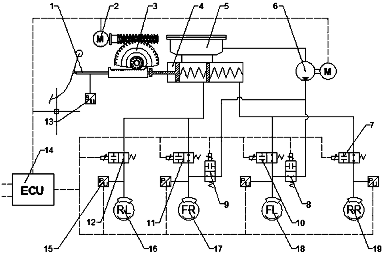
[0026] Such as figure 1 As shown, a brake fluid pressure precise adjustment system that meets the demand for wheel cylinder boosting is used to adjust the brake fluid pressure of the two front wheel cylinders and the two rear wheel cylinders of the vehicle. The system includes an electronic control unit 14 And the brake hydraulic pressure source, brake fluid pressure unit, auxiliary booster source, auxiliary booster unit and hydraulic pressure detection unit respectively connected thereto, the hydraulic pressure detection unit is connected to the front wheel cylinder and the rear wheel cylinder, and the brake hydraulic pressure The force unit is set with four lines. The four-way brake fluid pressure unit connects the front wheel cylinder and the rear wheel cylinder with the brake hydraulic pressure source respectively. The auxiliary booster unit is set with two or four lines. When two lines are set, the two lines The auxiliary supercharging unit connects the two front wheel cy...

Embodiment 2

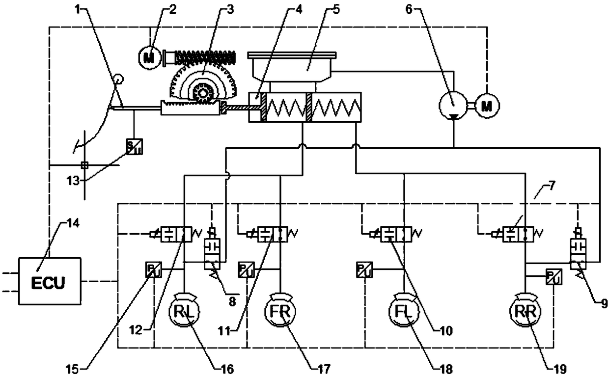
[0043] Such as figure 2 As shown, in this embodiment, the auxiliary booster unit of the brake fluid pressure precision adjustment system that meets the boosting requirements of the wheel cylinders is provided with two circuits and is respectively connected to two rear wheel cylinders, that is, the left rear wheel cylinder 18 and the right rear wheel cylinder 18. Wheel cylinder 19, other are all identical with embodiment 1.

[0044] In this embodiment, the specific working principle of the brake fluid pressure precise adjustment system that meets the demand of wheel cylinder boosting is as follows:

[0045] (1) Conventional braking conditions

[0046] When the electronic control unit 14 receives the normal braking command, the normally open solenoid valves 10 and 11 are in a power-off state, and the front wheel cylinders communicate with the brake master cylinder 4 . The normally open solenoid valves 7 and 12 are energized, and the rear wheel cylinders are disconnected from ...

Embodiment 3

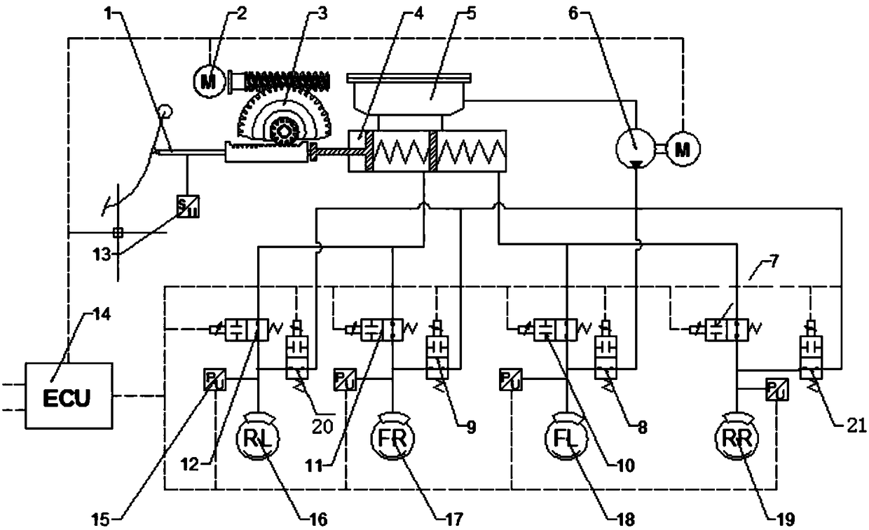
[0056] Such as image 3 As shown, in this embodiment, the brake fluid pressure precision adjustment system that meets the demand for wheel cylinder boosting is equipped with four auxiliary booster units, and the four auxiliary booster units respectively connect the front wheel cylinder and the rear wheel cylinder with the auxiliary booster Pressure source connection, all the other are the same as embodiment 1.

[0057] In this embodiment, the specific working principle of the brake fluid pressure precise adjustment system that meets the demand of wheel cylinder supercharging is similar to that of Embodiment 1 and Embodiment 2. Since the front wheel cylinder and the rear wheel cylinder are equipped with two sets of supercharging One set is a boosting and reducing mechanism consisting of a brake hydraulic source and a brake fluid pressure unit, and the other is an auxiliary boosting mechanism consisting of an auxiliary boosting source and an auxiliary boosting unit. During the c...


PUM


Abstract

The invention relates to a brake fluid pressure precise regulation system for satisfying the pressurization requirement of a wheel cylinder. The system comprises an electronic control unit, a brake hydraulic pressure source, a brake fluid pressure unit, an auxiliary booster source, an auxiliary pressurizing unit and a hydraulic pressure detecting unit, wherein the brake hydraulic pressure source,the brake fluid pressure unit, the auxiliary booster source, the auxiliary pressurizing unit and the hydraulic pressure detecting unit are connected with the electronic control unit. The hydraulic pressure sensing unit is connected with the front wheel cylinder and the rear wheel cylinder. The brake fluid pressure unit is four-way, and the auxiliary supercharging unit connects the front wheel cylinder or the rear wheel cylinder with the auxiliary supercharging source when the auxiliary supercharging unit is arranged in two or four paths, and the auxiliary supercharging unit connects the frontwheel cylinder or the rear wheel cylinder with the auxiliary supercharging source when the auxiliary supercharging unit is arranged in four paths, the auxiliary supercharging unit connects the front wheel cylinder and the rear wheel cylinder with the auxiliary supercharging source. When decompression is required, the brake hydraulic unit operates to decompress, when supercharging is required, thebrake hydraulic unit operates to supercharge, and the auxiliary supercharging unit operates to supercharge. Compared with the prior art, the invention has two sets of pressurizing mechanisms, and thestability and the safety are improved.

Description

technical field [0001] The invention relates to an automobile brake control system, in particular to a brake fluid pressure precise adjustment system meeting the demand for boosting wheel cylinders. Background technique [0002] The braking system is a vital system related to the safety performance of the vehicle, and its performance will directly affect the driving safety performance of the vehicle. A traditional braking system usually consists of a brake pedal, vacuum booster, brake master cylinder, ESC / ABS, brake wheel cylinder and its corresponding pipelines. The whole system is relatively complex, and is at a disadvantage in volume, quality and integration. Moreover, as the efficiency of the engine continues to improve, the degree of vacuum it can provide to the vacuum booster becomes more and more limited. In order to make up for this problem caused by high-efficiency engines, many vehicles adopt an additional vacuum pump to increase the vacuum. However, this soluti...

Claims


Application Information

Patent Timeline
Patent Type & Authority Applications(China)
IPC IPC(8): B60T13/74
CPCB60T13/745
Inventor 熊璐韩伟杨兴余卓平
Owner TONGJI UNIV
Why Eureka
Try Eureka