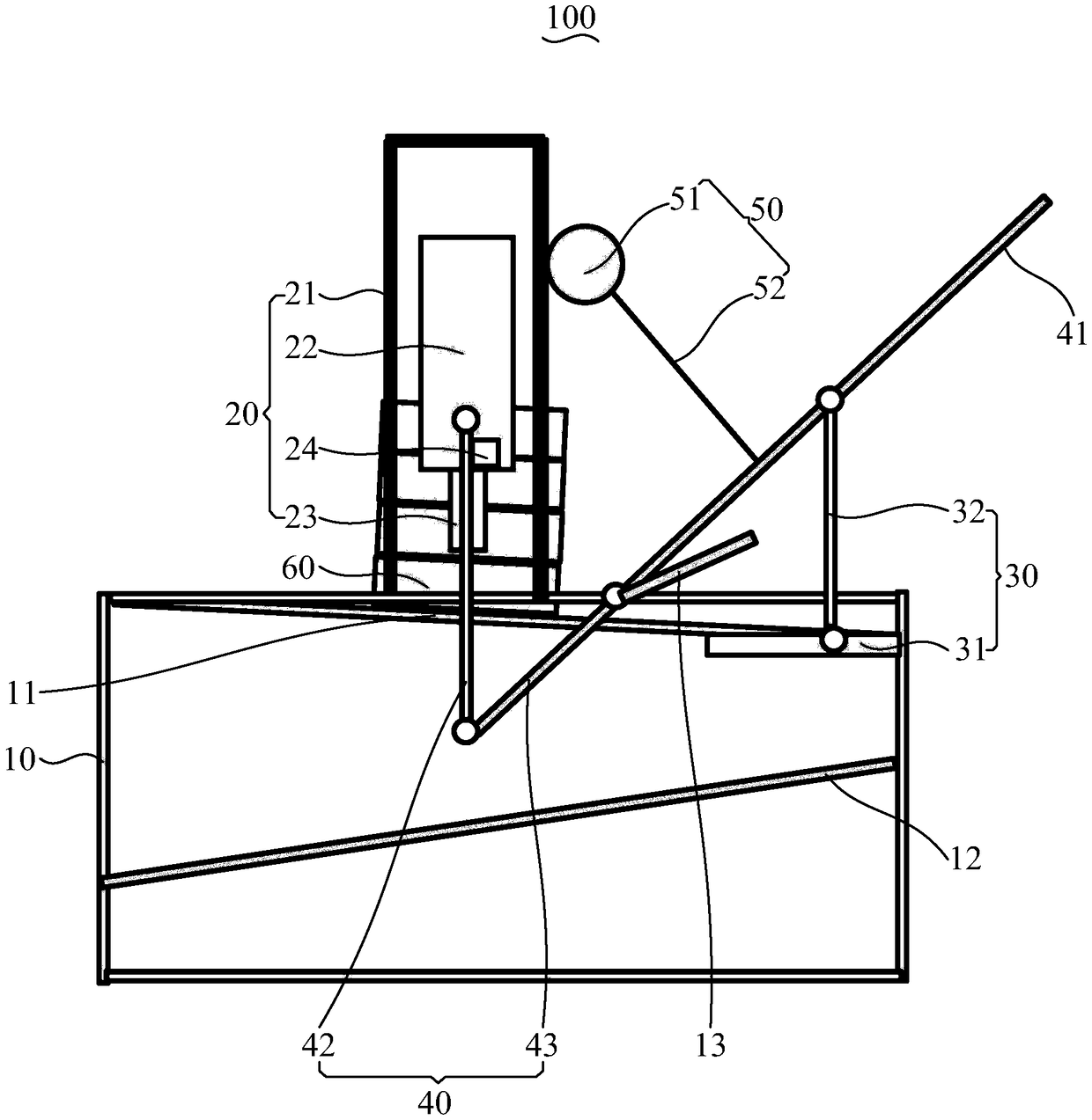
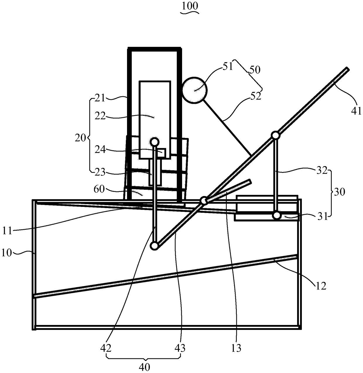
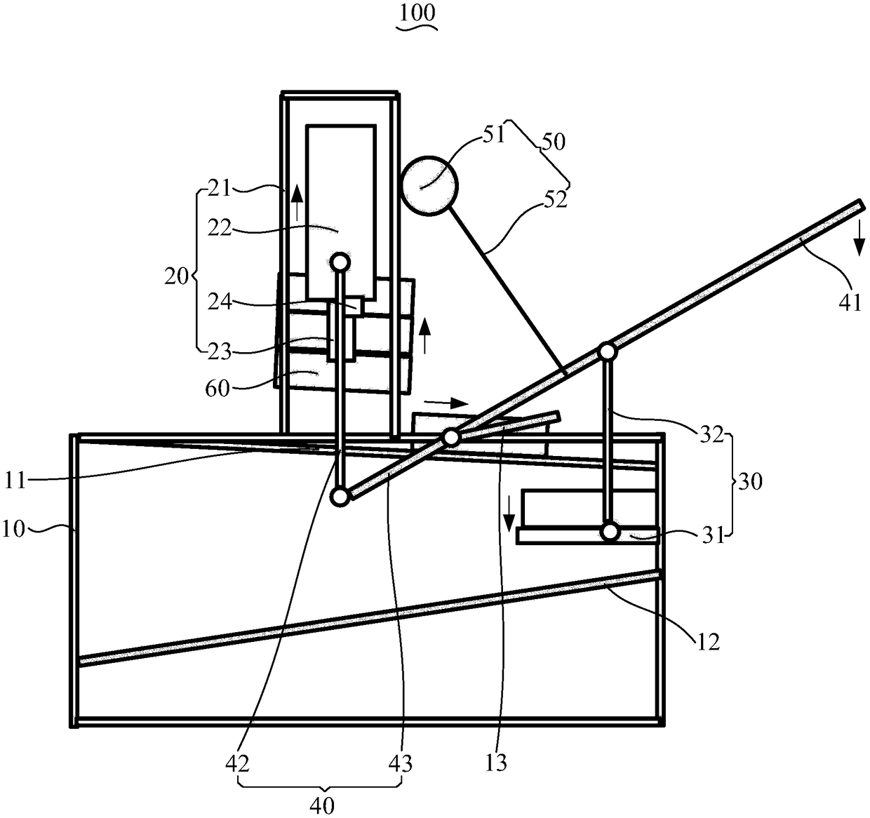
Powerless pile separation device

A technology of power and mounting frame, applied in the direction of destacking, transportation and packaging of objects, conveyors, etc., can solve the problems of large space occupation, inconvenient production, large size, etc., and achieve the effect of efficient operation, convenient operation and simple structure

Active Publication Date: 2019-01-08
GAC TOYOTA MOTOR
View PDF7 Cites 4 Cited by
  • Summary
  • Abstract
  • Description
  • Claims
  • Application Information

AI Technical Summary

Problems solved by technology

The existing stacking devices are not only complex in structure, but also large in size and take up a lot of space. Many of the stacking devices are operated

Method used


Image

  • Powerless pile separation device
  • Powerless pile separation device
  • Powerless pile separation device

Examples


Example Embodiment

[0043] The technical solutions in the embodiments of the present invention will be clearly and completely described below in conjunction with the accompanying drawings in the embodiments of the present invention. Obviously, the described embodiments are only a part of the embodiments of the present invention, rather than all the embodiments. Based on the embodiments of the present invention, all other embodiments obtained by those of ordinary skill in the art without creative work shall fall within the protection scope of the present invention.

[0044] It should be noted that all directional indications (such as up, down, left, right, front, back...) in the embodiments of the present invention are only used to explain the relationship between the components in a particular posture (as shown in the accompanying drawings). If the relative position relationship, movement situation, etc. change, the directional indication will change accordingly.

[0045] In the present invention, unl...


PUM


Abstract

The invention discloses a powerless pile separation device. The powerless pile separation device comprises a machine body, a pile separation module, a conveying module and a connecting rod module, wherein the machine body is provided with a first slide way and a second slide way arranged at intervals; the first slide way and the second slide way are used for conveying goods containers; the pile separation module is connected with the machine body, is arranged above the first slide way, and is used for separating the goods containers on the first slide way; the conveying module is arranged between the first slide way and the second slide way, and is used for conveying the goods containers to the second slide way after separation by the pile separation module; the connecting rod module is rotationally arranged on the machine body; one end of the connecting rod module is connected with the pile separation module, and the other end of the connecting rod module is connected with the conveying module; the connecting rod module is provided with a handle; and when the handle pulls the connecting rod module to move, the connecting rod module drives the pile separation module to separate thegoods containers on the first slide way, and the connecting rod modules drives the conveying module to convey the goods containers, separated on the first slide way, to the second slide way. The powerless pile separation device is simple and small in structure and convenient for operation and application to a small production line.

Description

technical field [0001] The invention relates to the technical field of stacking devices, in particular to a non-powered stacking device. Background technique [0002] At present, in the logistics distribution of large-scale production lines or in the factory process room, it is usually necessary to separate the boxes for subsequent processing and use. The existing stacking devices are not only complex in structure, but also large in size and take up a lot of space. Many of the stacking devices are operated by mechanization, resulting in higher requirements for operators, and it is not conducive to use in small manual production lines. Inconvenience to production. Contents of the invention [0003] The main purpose of the present invention is to provide a non-powered stacking device, aiming to provide a simple structure, small and exquisite, and easy to operate, easy to apply in small-scale production line of the non-powered stacking device. [0004] In order to achieve t...

Claims


Application Information

Patent Timeline
IPC IPC(8): B65G47/90B65G59/02B65G11/20
CPCB65G11/203B65G47/901B65G59/02B65G2201/0258
Inventor 刘嘉豪
Owner GAC TOYOTA MOTOR
Why Eureka
Try Eureka