
Composite insulation system

Pending Publication Date: 2019-04-25
NELSON GLOBAL PROD
View PDF0 Cites 2 Cited by
  • Summary
  • Abstract
  • Description
  • Claims
  • Application Information

AI Technical Summary

Benefits of technology

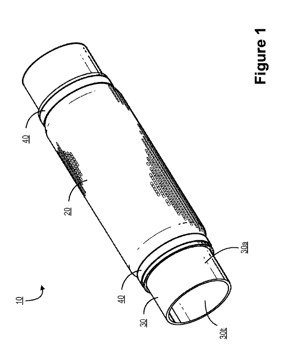
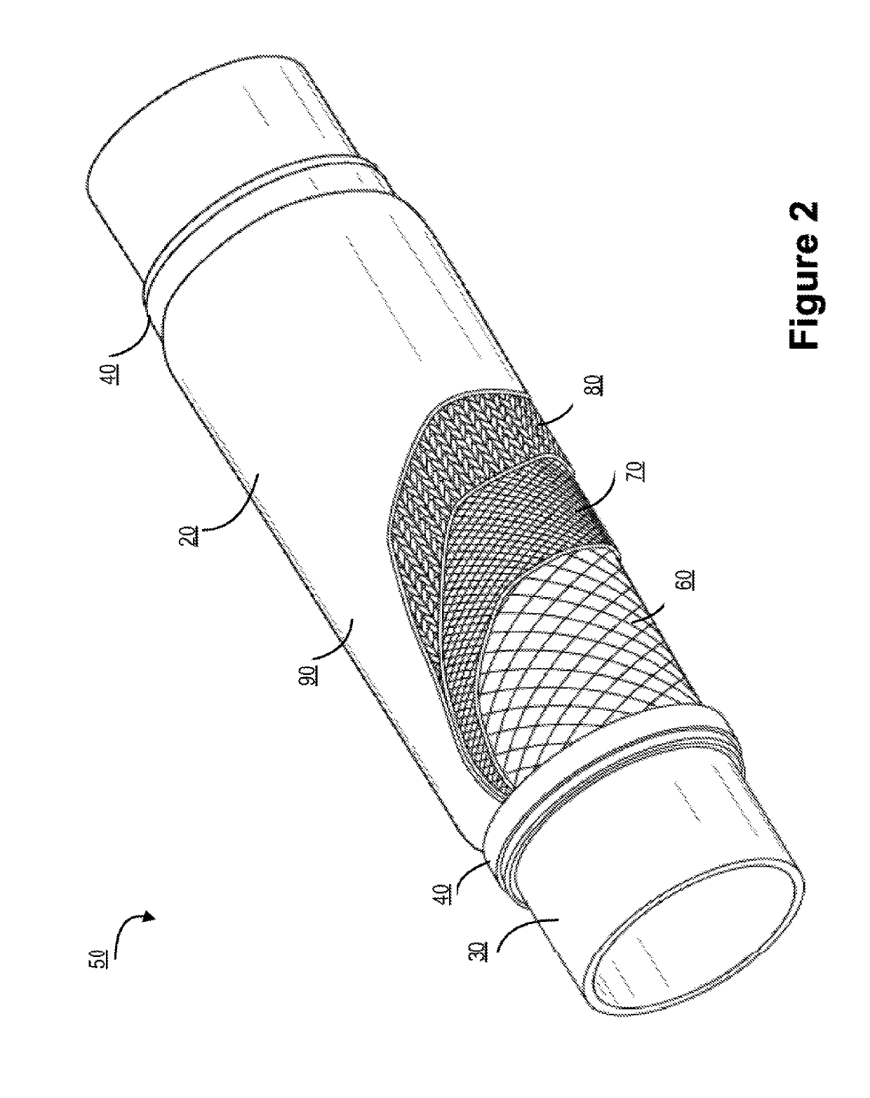
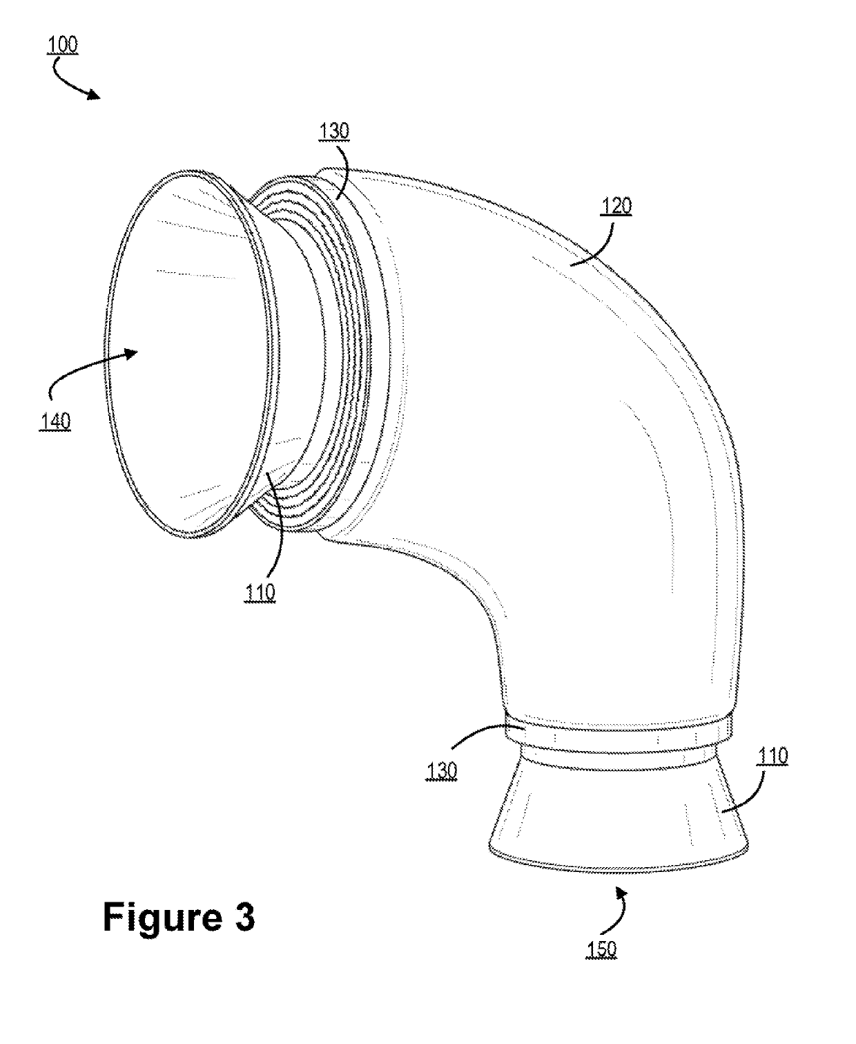
The present invention provides an insulation system for components that can be easily applied to individual pipes or efficiently run on high-volume part configurations. The system includes a flexible self-molding cover, a structural reinforcement layer, and a liquid polymer matrix solution that can be applied to the structural reinforcement layer and self-molding fiber cover and cured to form the fiber-reinforced composite insulation system. The technical effect of this invention is a highly customizable, efficient, and self-molding insulation system that provides structural support, insulation, or protection to components.

Problems solved by technology

Typically, the insulation is not flexible or adaptable for different configurations.
Current methods typically require part specific tooling or manually intensive installation methods and typically do not perform at the desired level in one or more areas.
Often pipe insulation is uniform throughout the part to minimize application complexity, yet the thermal loss exhibited throughout the system is non-uniform.
Wrapped insulation often involves multiple layers of wrapped materials that is extremely labor intensive.
While a high degree of compression during molding can create a highly consolidated composite with minimal void to maximize strength, this is not always necessary or desirable.
Historically, fiber reinforced composites have been limited to high volume and or high cost applications.
The cost of molding equipment must either be recovered through a large volume of parts or through high costs for low volume parts.
While these overcome the need for a two-part mold, wrapped tapes are subject to a number of issues including inconsistent compression, uneven thickness, discontinuous coverage along the length, tape-edge weakness and poor appearance.
In this way, each different exhaust pipe configuration requires a unique set of molds at a significant tooling cost each.
Furthermore, the methods currently used in exhaust systems have various limitations.
For example, insulation covers tend to rip or fray easily if caught.
Resin fiber rheology is limited to that of the resin fiber production process.
Moreover, the amount of resin that can be used to stabilize and strengthen the system is limited by resin fibers.

Method used


Image

  • Composite insulation system
  • Composite insulation system
  • Composite insulation system

Examples


Embodiment Construction

[0084]Embodiments of the present invention will now be described more fully hereinafter with reference to the accompanying drawings, in which some, but not all, embodiments of the invention are shown. Indeed, the invention may be embodied in many different forms and should not be construed as limited to the embodiments set forth herein; rather, these embodiments are provided so that this disclosure will satisfy applicable legal requirements. Where possible, any terms expressed in the singular form herein are meant to also include the plural form and vice versa, unless explicitly stated otherwise. Also, as used herein, the term “a” and / or “an” shall mean “one or more,” even though the phrase “one or more” is also used herein. Furthermore, when it is said herein that something is “based on” something else, it may be based on one or more other things as well. In other words, unless expressly indicated otherwise, as used herein “based on” means “based at least in part on” or “based at l...


PUM

PropertyMeasurementUnit
Dispersion potentialaaaaaaaaaa
Flow rateaaaaaaaaaa
Rheological propertiesaaaaaaaaaa

Abstract

Embodiments of the present invention provide a self-molding composite system for insulation and covering operations. The self-molding composite system may be cured to form any desired shaped for insulation and covering operations. The composite system comprises one or more layers that may create a rigid layered composite when cured. The one or more layers of the composite system may include at least one structural reinforcement layer that is a braided, knit, or non-woven fiber based substrate, an interstitial matrix layer, and customizable top coat. The customizable top coat may be a solvent based polymer solution that includes various additives that may include color pigments, additives for additional abrasion protection, additives for thermal protection, and / or additives for creating various textures or visible appearances to the composite system.

Description

FIELD OF THE INVENTION[0001]The present invention typically relates to, in general, a customizable pipe insulation system for industrial, automotive and recreational vehicle applications that involve transport of fluids through pipes and ducts.BACKGROUND[0002]Insulated pipes in the industrial and transportation sectors often are unique to a particular application and they are often low volume parts with annual requirements below a thousand units per year. In many applications, the insulation is required to be manufactured specifically for the desired pipe geometry and the specific insulation requirements of the application. Typically, the insulation is not flexible or adaptable for different configurations. Often the insulation is required to perform thermal insulation, pipe protection, be astatically acceptable and be durable for long durations. Current methods typically require part specific tooling or manually intensive installation methods and typically do not perform at the des...

Claims


Application Information

Patent Timeline
IPC IPC(8): F16L59/02F16L59/14B32B1/08B32B5/26B32B7/12
CPCF16L59/021F16L59/14B32B1/08B32B5/26B32B7/12B32B2307/304B32B2597/00F16L59/029F16L5/14
Inventor GOULET, ROBERT JACQUE
Owner NELSON GLOBAL PROD
Learn More