
Device used for long-distance large-pipe-diameter pipeline water delivery pipeline tail end and having function of removing water hammer in pipeline

A water pipeline and large-diameter technology, which is applied in the pipeline system, mechanical equipment, gas/liquid distribution and storage, etc., can solve problems that affect the safe and regular operation of the pipeline, strong vibration of the pipeline system, damage to the pipeline system, etc., to avoid The loss of water resources, the effect of increasing the degree of automation and reducing human intervention

Pending Publication Date: 2019-12-31
YUNNAN DAHONGSHAN PIPELINE
View PDF0 Cites 1 Cited by
  • Summary
  • Abstract
  • Description
  • Claims
  • Application Information

AI Technical Summary

Problems solved by technology

During normal operation, the water head of the piezometer tube is smaller than the static head, but after the gate and valve on the pipeline are closed, the maximum static head in the pipe is the maximum drop of the terrain. The larger the drop, the higher the pressure on the pipeline. When the gate, valve in the pipeline When an abnormal shutdown occurs, it is easy to generate a large water hammer pressure, resulting in a pipeline burst accident
For special multi-fluctuating gravity flow pipelines, flow cavities often occur at high points and turning points of the pipeline, which can easily cause flow breakage to bridge water hammer, and the instantaneous pressure generated by water hammer can reach dozens of times or even the normal working pressure in the pipeline. This large pressure fluctuation can cause strong vibration and noise in the pipeline system, and may damage the valve joint, which has a great destructive effect on the pipeline system and seriously affects the safe and regular operation of the pipeline.

Method used


Image

  • Device used for long-distance large-pipe-diameter pipeline water delivery pipeline tail end and having function of removing water hammer in pipeline

Examples


Embodiment Construction

[0022] All features disclosed in this specification, or steps in all methods or processes disclosed, may be combined in any manner, except for mutually exclusive features and / or steps.

[0023] Any feature disclosed in this specification (including any appended claims, abstract), unless otherwise stated, may be replaced by alternative features which are equivalent or serve a similar purpose. That is, unless expressly stated otherwise, each feature is one example only of a series of equivalent or similar features.

[0024] In the description of the present invention, it should be understood that the orientation or positional relationship indicated by the terms "upper", "lower", "left", "right" etc. is based on the orientation or positional relationship shown in the drawings, and is only for It is convenient to describe the present invention and simplify the description, but not to indicate or imply that the device or element referred to must have a specific orientation, be cons...


PUM


Abstract

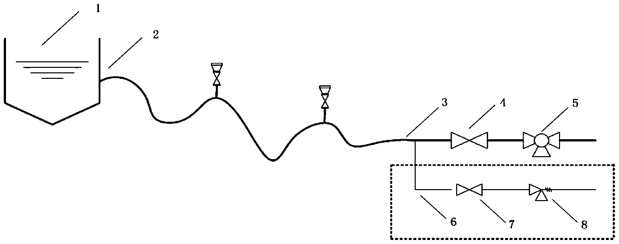
The invention discloses a device used for a long-distance large-pipe-diameter pipeline water delivery pipeline tail end and having a function of removing a water hammer in a pipeline. The device comprises a pond, a pipeline water outlet front end, a pipeline water outlet tail end, a first service valve, a flow adjusting valve, a bypass pipe, a second service valve and a pressure fluctuation pre-check valve. The pipeline water outlet front end is connected with the pond, the first service valve and the flow adjusting valve are sequentially arranged on the pipeline water outlet tail end, the bypass pipe and the pipeline water outlet tail end are arranged in parallel, and the second service valve and the pressure fluctuation pre-check valve are sequentially arranged in the liquid flowing direction on the bypass pipe. Safe, stable and efficient running of water delivery system equipment can be ensured, the major accident of the water delivery and transfer pipeline system can be effectivelyreduced, the phenomenon of water source losing or damage to the surrounding ecological environment due to pipe blasting can be avoided, the water hammer generated by non-normal closing of a brake andother valves in the pipeline can be removed, manual intervention is reduced, and the automation degree is improved.

Description

technical field [0001] The invention relates to the field of water hammer control of large-scale pipeline water delivery projects and pump stations, in particular to a device for eliminating water hammer in the pipeline at the end of a long-distance large-diameter pipeline water delivery pipeline. Background technique [0002] Large-scale pipeline water delivery projects often use the natural terrain drop to deliver water by gravity flow. Since there is no water pump to pressurize the gravity flow water delivery pipeline, the pressure at low flow rate is higher than that at high flow rate. During normal operation, the water head of the piezometer tube is smaller than the static head, but after the gate and valve on the pipeline are closed, the maximum static head in the pipe is the maximum drop of the terrain. The larger the drop, the higher the pressure on the pipeline. When the gate, valve in the pipeline When an abnormal shutdown occurs, it is easy to generate a large wat...

Claims


Application Information

Patent Timeline
IPC IPC(8): F17D3/01F17D1/08
CPCF17D3/01F17D1/08
Inventor 陈建军张向波李剑勇张巍周江松韩军刚赵增佳李剑锋马波
Owner YUNNAN DAHONGSHAN PIPELINE
Learn More