Al technical title is built by PatSnap Al team. It summarizes the technical point description of the patent document.
A technology of lifting car and cutting die, which is applied in the direction of lifting frame, lifting device, etc., can solve the problems that the transfer mechanism does not have a steering function, cannot meet the needs of use, and the operation of the cutting die lifting car is not stable enough, so as to achieve compact structure and easy movement , the effect of easy operation
Active Publication Date: 2019-01-08
YANCHENG HUASEN MACHINERY
View PDF6 Cites 1 Cited by
Summary
Abstract
Description
Claims
Application Information
AI Technical Summary
This helps you quickly interpret patents by identifying the three key elements:
Problems solved by technology
Method used
Benefits of technology
Problems solved by technology
[0002] The knife mold is the mold for punching products. A box is a piece of flat paper when printing. To make a box after printing, you need to make a flat mold that is the same as the box for stamping. This mold is the printing knife mold. During the process of placing and taking out the cutting dies, it is necessary to transport and transfer the cutting dies. The existing die cutting lift car does not run smoothly enough, and the transfer mechanism does not have a steering function, which cannot meet the needs of use.
Method used
Image
Click on the blue label to locate the original text in one second.
Reading with bidirectional positioning of images and text.
Examples
Embodiment Construction
[0017] The following will clearly and completely describe the technical solutions in the embodiments of the present invention with reference to the accompanying drawings in the embodiments of the present invention. Obviously, the described embodiments are only some, not all, embodiments of the present invention. Based on the embodiments of the present invention, all other embodiments obtained by persons of ordinary skill in the art without making creative efforts belong to the protection scope of the present invention.
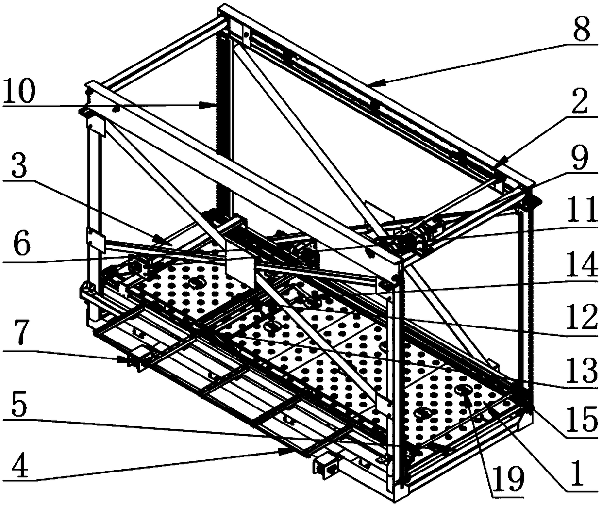
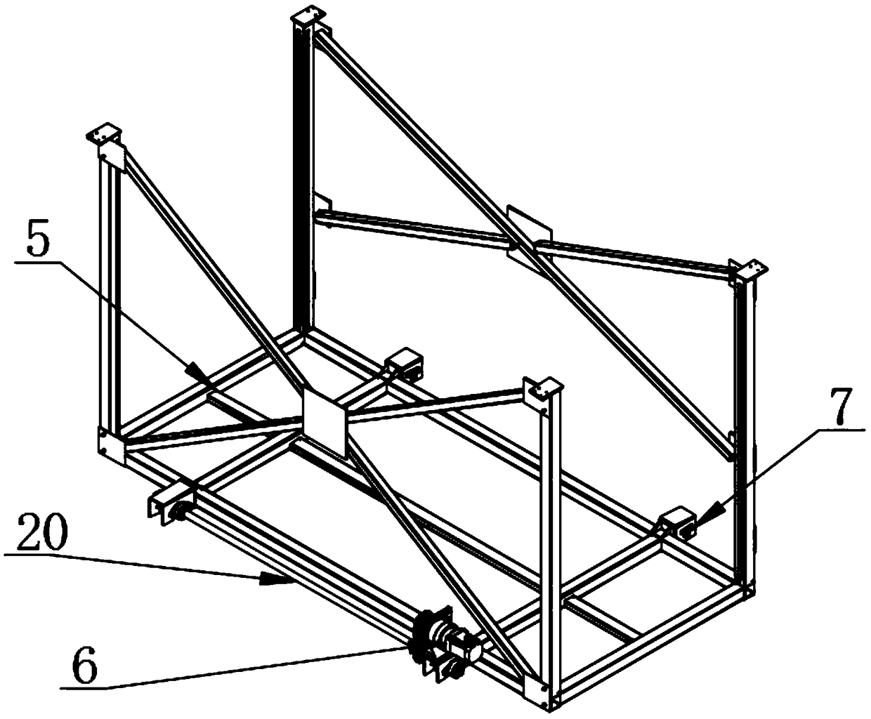
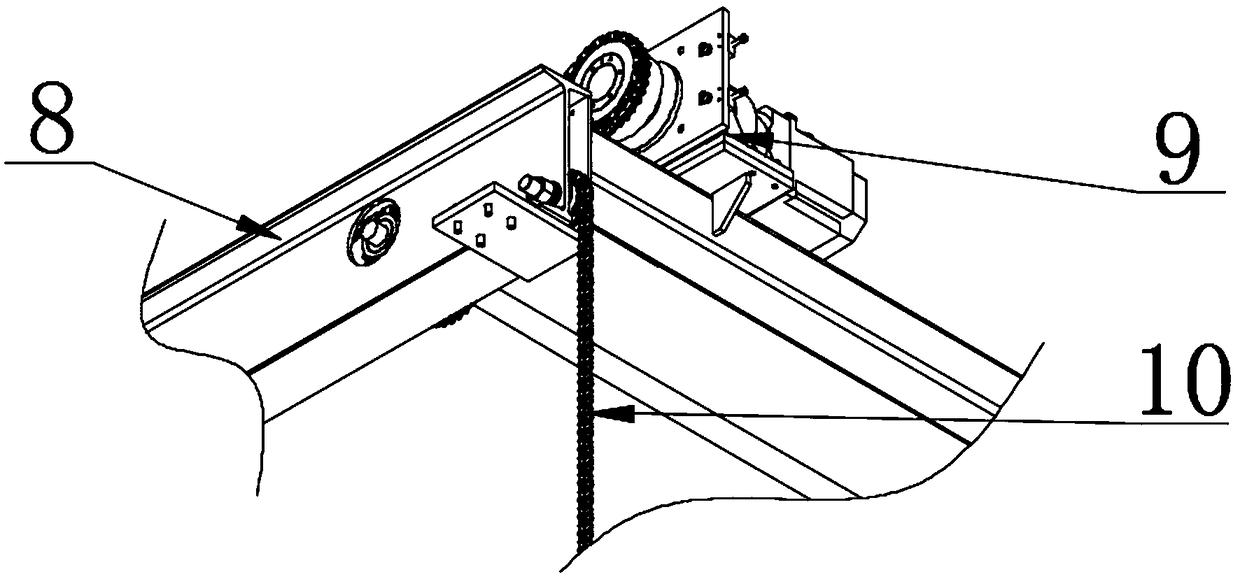
[0018] see Figure 1-5 , the present invention provides a technical solution: die lifter, including a lifting mechanism 2, a die moving mechanism 3, a die guide mechanism 4, a base frame 5, a base motor 6, a track wheel 7, an upper beam 8, a chain 10, Drive shaft 20 and sprocket wheel 21, base plate motor 6 are fixedly installed on the side motor mounting seat of base plate frame 5, the output shaft of base plate motor 6 is connected with drive shaft 20 by cha...
PUM
Abstract
The invention discloses a cutting die lifting vehicle. The lifting vehicle comprises a lifting mechanism, a cutting die moving mechanism, a cutting die guide mechanism, a bottom plate frame, a bottomplate motor, a rail wheel, an upper cross beam, a chain, a transmission shaft and a chain wheel; the lifting mechanism is arranged at the top of the bottom plate frame, and is fixedly arranged on oneside of the upper cross beam, and the lifting mechanism is composed of a lifting motor, the chain, the transmission shaft and the chain wheel; the cutting die moving mechanism is composed of a cuttingdie plate, a drag hook moving motor, a drag hook air cylinder, a cutting die pulling support, a drag hook, a synchronous belt and a synchronous belt wheel; and the cutting die guide mechanism is composed of a micro motor, a steering air cylinder and a cutting die conveying wheel. According to the cutting die lifting vehicle, a cutting die is lifted through the lifting mechanism, the structure iscompact, and the operation is convenient; the cutting die moving mechanism is stable in operation, the moving process is smooth, and the cutting die is convenient to move; the cutting die guide mechanism steers the cutting die, and conveying in different directions is facilitated; and the chain transmission and the belt transmission are adopted on the whole, the operation is stable, and the energyloss is small.
Description
technical field [0001] The invention relates to the technical field of die-cutting production equipment, in particular to a die-cutting lifting vehicle. Background technique [0002] The knife mold is the mold for punching products. A box is a piece of flat paper when printing. To make a box after printing, you need to make a flat mold that is the same as the box for stamping. This mold is the printing knife mold. During the process of placing and taking out the dies, the dies need to be transported and transferred. The existing die lifter does not run smoothly enough, and the transfer mechanism does not have a steering function, which cannot meet the needs of use. Contents of the invention [0003] The object of the present invention is to provide a die lifting vehicle to solve the problems raised in the above-mentioned background technology. [0004] In order to solve the above-mentioned technical problems, the present invention provides the following technical solution...
Claims
Application Information
Patent Timeline
Application Date:The date an application was filed.
Publication Date:The date a patent or application was officially published.
First Publication Date:The earliest publication date of a patent with the same application number.
Issue Date:Publication date of the patent grant document.
PCT Entry Date:The Entry date of PCT National Phase.
Estimated Expiry Date:The statutory expiry date of a patent right according to the Patent Law, and it is the longest term of protection that the patent right can achieve without the termination of the patent right due to other reasons(Term extension factor has been taken into account ).
Invalid Date:Actual expiry date is based on effective date or publication date of legal transaction data of invalid patent.