
Shadowless lamp

A technology of shadowless lamps and lamp beads, which is applied in lighting and heating equipment, fixed lighting devices, treatment rooms, etc., can solve the problems of limited scope of application, limited adjustment methods, and inability to achieve the effect of shadow elimination, so as to reduce the influence of shadows and the number of steps Controllable and adjustable focus effect

Active Publication Date: 2019-01-08
JILIN UNIV
View PDF18 Cites 2 Cited by
  • Summary
  • Abstract
  • Description
  • Claims
  • Application Information

AI Technical Summary

Problems solved by technology

However, the shadowless lamp with this structure can only be adjusted by rotation and vertical height, and the adjustment method is limited and cannot achieve better shadow elimination effect, which limits its scope of application.

Method used


Image

  • Shadowless lamp
  • Shadowless lamp
  • Shadowless lamp

Examples


Embodiment 1

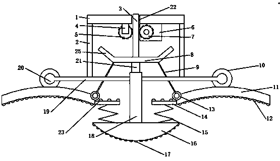
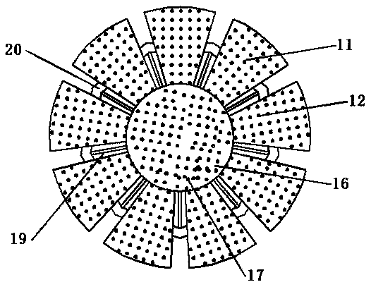
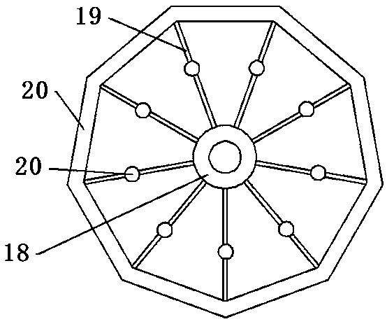
[0022] refer to Figure 1-5, a specific embodiment of the present invention includes a circular support plate 1, the bottom of the support plate 1 is vertically connected with several first connecting rods 2 arranged in a ring, and the bottom of the first connecting rod 2 is vertically connected with a second connecting rod 19, a plurality of second connecting rods 19 are arranged in a ring, and the inner sides of the plurality of second connecting rods 19 are fixedly connected with a fixed pipe 18, and the outer sides of adjacent second connecting rods 19 are connected to each other through the third connecting rod 20, and the fixed pipe 18 The bottom of the fixed pipe 18 is connected with a fixed base 16, and the top of the fixed pipe 18 is movably inserted with a plunger 21, the top of the plunger 21 is connected with a disc 8, the center of the top surface of the disc 8 is connected with a rack 3, and the bottom of the support plate 1 Also connected with the first support ...

Embodiment 2

[0025] refer to Image 6 , this embodiment is further improved on the basis of embodiment 1. During the applicant's many tests, the applicant found that the elastic constant and the initial length of the first spring 15 will change after a long time of use, resulting in the deviation of the angle of the fixing plate 14 . In order to solve this problem, a sleeve 26 is sleeved on the outside of the first spring 15, and the sleeve 26 is fixed on the top of the holder 16. The side wall of the sleeve 26 is connected with a rubber damping strip 28 through an adjusting bolt 27, and the rubber damping strip 28 is connected to the first spring 15. A spring 15 is in contact. A groove 29 is provided on the surface of the rubber damping strip 28 , and the limiting strip 31 is connected to the groove 29 through the second spring 30 , and the surface of the limiting strip 31 is provided with a flange 32 that engages with the first spring 15 . The rubber damping strip 28 is driven by the a...


PUM


Abstract

The invention discloses a shadowless lamp. The shadowless lamp comprises a supporting plate, first connecting rods, second connecting rods and a fixing pipe, wherein the outer sides of adjacent secondconnecting rods are interconnected through third connecting rods; a fixing seat is connected to the bottom part of the fixing pipe, and an inserting rod is movably inserted into the top part of the fixing pipe; a circular plate is connected to the upper part of the inserting rod, and a rack is connected to the center of the top surface of the circular plate; a first support and a motor are connected to the lower part of the supporting plate; a first gear is shafted to the first support; a second gear is connected to the motor; two sides of the rack are correspondingly engaged with the first gear and the second gear; sleeve rings movably sleeve the third connecting rod; a sector plate is fixedly connected to the bottom part of each sector ring; a plurality of lamp beads are connected to the lower parts of the sector plates; fixing plates are connected to the inner sides of the sector plates; first springs are connected between the fixing plates and the fixing seats; and connecting ropes are connected between the inner sides of the sector plates and the circular plate. The shadowless lamp overcomes the shortages in the prior art and is high in adjusting effect.

Description

technical field [0001] The invention relates to a lamp, especially a shadowless lamp. Background technique [0002] The shadowless lamp, also known as the surgical shadowless lamp, is used to illuminate the surgical site and can best observe small, low-contrast objects at different depths in the incision and body cavity. Since the operator's head, hands and instruments may cause interference shadows on the surgical site, the surgical shadowless lamp should be designed to eliminate shadows as much as possible and minimize color distortion. Chinese invention patent CN 207179368 U discloses a surgical shadowless lamp. The surgical shadowless lamp with this structure adjusts the shadow and focal length of the surgical shadowless lamp through the height adjustment motor and the height adjustment disc. However, the shadowless lamp with this structure can only be adjusted by rotation and vertical height, and the adjustment method is limited and cannot achieve better shadow elimin...

Claims


Application Information

Patent Timeline
Patent Type & Authority Applications(China)
IPC IPC(8): F21S8/00F21V19/00F21V19/02F21W131/205
CPCF21S8/00F21V19/00F21V19/02F21W2131/205
Inventor 刘素杰
Owner JILIN UNIV
Learn More