
Frequency change signal two-dimensional direction finding method and device adopting two sensors

A sensor and frequency-changing technology, which is applied in the direction of instruments, measuring devices, and directional devices for measuring directions, etc., can solve problems such as the inability to realize the direction-finding of frequency-variable signals, phase ambiguity resolution, and time-consuming iterative calculations.

Active Publication Date: 2019-01-08
SOUTHWEST CHINA RES INST OF ELECTRONICS EQUIP
View PDF8 Cites 13 Cited by
  • Summary
  • Abstract
  • Description
  • Claims
  • Application Information

AI Technical Summary

Problems solved by technology

The currently used two-sensor rotating interferometer direction finding method has problems such as phase ambiguity resolution, time-consuming iterative calculation, multi-target resolution, contribution of data samples with different signal-to-noise ratios, and convergence judgment are not considered.
Moreover, the existing method cannot realize the direction finding of the frequency conversion signal, and does not consider the problem of signal-to-noise ratio of different sampling data

Method used


Image

  • Frequency change signal two-dimensional direction finding method and device adopting two sensors
  • Frequency change signal two-dimensional direction finding method and device adopting two sensors
  • Frequency change signal two-dimensional direction finding method and device adopting two sensors

Examples


Embodiment Construction

[0073] All features disclosed in this specification, or steps in all methods or processes disclosed, may be combined in any manner, except for mutually exclusive features and / or steps.

[0074] Any feature disclosed in this specification, unless specifically stated, can be replaced by other alternative features that are equivalent or have similar purposes. That is, unless expressly stated otherwise, each feature is one example only of a series of equivalent or similar features.

[0075] Aiming at the problems of time-consuming calculation, inability to process variable-frequency signals, and failure to consider different contributions of signals with different signal-to-noise ratios in existing methods, the present invention provides a two-dimensional direction-finding method and device for frequency-variable signals using two rotating sensors.

[0076] The coordinates are defined as follows:

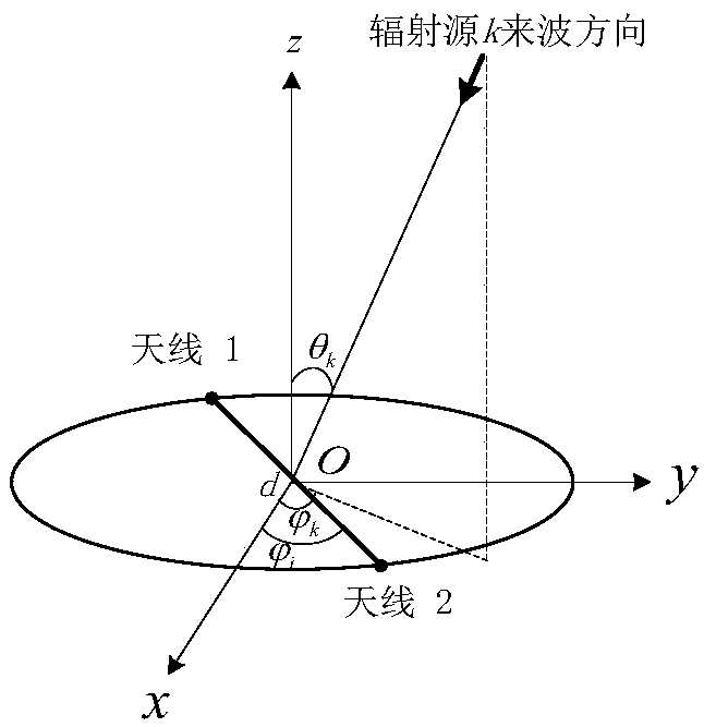
[0077] like figure 1 As shown, the incident direction of the kth signal is: azimu...


PUM


Abstract

The invention discloses a frequency change signal two-dimensional direction finding method and device adopting two sensors. The method comprises the following steps of acquiring the collected phase differences phi n, the frequencies fn and the signal-to-noise ratios SNRn of the two sensors; randomly dividing the data of the collected phase differences into K groups; for each group of the collectedphase differences, calculating weighted distances between complex numbers composed of the collected phase differences and complex numbers composed of phase differences corresponding to angles on an incident angle grid, thereby generating two-dimensional distance matrixes; searching for each distance matrix to obtain a matrix serial number corresponding to a minimum value in each distance matrix;defuzzifying the collected phase differences to obtain a non-fuzzy phase difference matrix; solving the two-dimensional incident angles; sequentially sorting K groups of the two-dimensional incident angles, and comparing a current result with a previous result; and if K comparison values L<1>-L<K> are all smaller than a threshold, outputting the current result, otherwise, according to the currentresult, generating K groups of theoretical phase differences, calculating the distances, defined in the description, between the collected phase differences phi n and the theoretical phase differencesdefined in the description, comparing the distances defined in the description, and re-classifying the phi n to the corresponding k-th group when the distance defined in the description is minimum.

Description

technical field [0001] The invention belongs to the technical field of radio monitoring, and relates to a two-dimensional direction-finding method of a phase interferometer, in particular to a two-dimensional direction-finding method and equipment for a plurality of frequency-varying signals using two rotating sensors. Background technique [0002] The phase interferometer is a direction finding method commonly used in the current direction finding system because of its high direction finding accuracy. [0003] Phase interferometers are divided into fixed arrays and time-varying arrays. The position of the unit antenna of the fixed phase interferometer is fixed, and the incident angle information of the incoming wave is obtained through the phase difference between the units. Two-dimensional angle measurement is based on three or four antenna phase value differences to form two sets of phase difference equations to solve two unknown quantities of two-dimensional incident an...

Claims


Application Information

Patent Timeline
Patent Type & Authority Applications(China)
IPC IPC(8): G01S3/46
CPCG01S3/46
Inventor 左乐胡泽华聂剑坤应钱诚王丽华
Owner SOUTHWEST CHINA RES INST OF ELECTRONICS EQUIP
Learn More