A fully differential Class D clamp recovery circuit

A recovery circuit, fully differential technology, applied to electrical components, generating electrical pulses, pulse duration/width modulation, etc., can solve problems such as errors and not very smooth output signals

Active Publication Date: 2019-01-08
WUHAN JUXIN MICROELECTRONICS CO LTD
View PDF5 Cites 4 Cited by
  • Summary
  • Abstract
  • Description
  • Claims
  • Application Information

AI Technical Summary

Problems solved by technology

[0007] To sum up, in the process of eliminating the 'ticking' noise caused by the second-order effect in the clamp recovery process in the prior art method, in method 1, both VP and VM are clamped at the Clipping state through logic control. Near Vcm, comparators A1 and A2 will inevitably have a delay. At this time, VP and VM may cross, which will cause the wrong judgment of the clamping judgment logic circuit. Switch back and forth to form sub-harmonic oscillation; method two, compared with method one, although it solves the problem of sub-harmonic oscillation, it still has the following defects, problem one: in figure 2 In the judging logic of whether the system shown is in the Clipping state, when the system is on the edge of Clipping, due to the delay of the comparator Comp in the loop, the pwm may appear later than the clkb, and the logic circuit will wrongly judge that the system is in the Clipping state. Clipping state, and then take corresponding actions, which will cause the output signal to be not very smooth when entering or exiting the Clipping state; Question 2: This method is not suitable for fully differential Class D, because the triangular wave in fully differential Class D is generally direct It is output by the oscillator, which is a fixed operating frequency, and the output of the second integrator is not mainly determined by the triangle wave, so it is not possible to control the time of the square wave current of the input or output capacitor C2 to control the output VM of the second integrator at Vcm Nearby purpose; although method 3 can be applied to fully differential Class D and THD is smaller than methods 1 and 2, its maximum output power is limited by the power supply voltage of the power tube, that is, the maximum output power is limited

Method used


Image

  • A fully differential Class D clamp recovery circuit
  • A fully differential Class D clamp recovery circuit
  • A fully differential Class D clamp recovery circuit

Examples


Embodiment Construction

[0030] The specific implementation manners of the present invention will be further described in detail below in conjunction with the accompanying drawings and embodiments. The following examples are used to illustrate the present invention, but are not intended to limit the scope of the present invention.

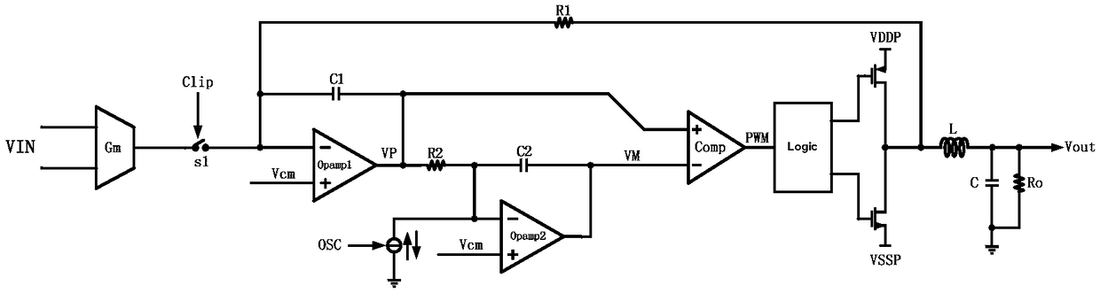
[0031] In this example, if Figure 10 As shown, a fully differential Class D clamp recovery circuit is proposed, including a fully differential Class D amplifier circuit and a clamp recovery circuit; the fully differential Class D amplifier circuit includes a first-stage integrator (i.e. Figure 10 OPAMP1 in), the second stage integrator (ie Figure 10 OPAMP2 in), PWM modulation comparator COMP ( Figure 10 COMP in), triangular wave generating circuit OSC, H-bridge; the clamp recovery circuit includes a Clipping detect module, a first comparator 2, a second comparator 3 and a third comparator 4;

[0032] The first-stage integrator is connected to the second-stage integr...


PUM


Abstract

An embodiment of the present invention provides a fully differential Class D clamp recovery circuit, As to whet that pwm signal between the two clk rising edge becomes high and whether the pwm signalbetween the two clk falling edge becomes low, whether the system enters the Clipping state or not can be judged according to whether the system enters or exits the Clipping state smoothly, which can avoid the false triggering of the Clipping state caused by the delay of the comparator Comp in the loop. By clamping the two outputs of the second integrator in the loop to a reference voltage slightlyabove the peak value of the triangular wave and slightly below the valley value of the triangular wave in the Clipping state, the subharmonic oscillation of the system in the Clipping state is prevented.

Description

technical field [0001] The present invention relates to the technical field of integrated circuit design, in particular to a fully differential Class D clamp recovery circuit. Background technique [0002] Audio amplifiers have a history of nearly 100 years, and the first application of the earliest tube amplifiers was audio amplifiers. Until now, audio amplifiers are constantly being updated and developed. Among them, Class D (Class D) amplifiers feature high efficiency, low power consumption, and small size. First, they become the first choice for audio amplifiers in battery-powered handheld consumer electronics and mobile phone applications. In the application of Class D amplifiers, in order to achieve sufficient output power, it is often required that the output range of the amplifier can reach rail-to-rail. For example: the datasheet of some audio power amplifiers will give the output power when the total harmonic distortion THD = 10%, THD = 10% means: the Class D out...

Claims


Application Information

Patent Timeline
Patent Type & Authority Applications(China)
IPC IPC(8): H03K3/013H03K3/017H03K7/08
CPCH03K3/013H03K3/017H03K7/08
Inventor 卢杰
Owner WUHAN JUXIN MICROELECTRONICS CO LTD
Why Eureka
Try Eureka