Laser beam and machine tool shaft moving direction parallelism adjusting method

A technology of moving direction and debugging method, applied in laser welding equipment, welding equipment, metal processing equipment and other directions, can solve the problems of high cost and cumbersome adjustment process, and achieve the effect of simple operation, wide application range, and fast and simple adjustment process.

Active Publication Date: 2019-01-11
XI'AN INST OF OPTICS & FINE MECHANICS - CHINESE ACAD OF SCI
View PDF8 Cites 3 Cited by
  • Summary
  • Abstract
  • Description
  • Claims
  • Application Information

AI Technical Summary

Problems solved by technology

[0004] The purpose of the present invention is to solve the problem of high cost and cumbersome adjustment process of the existing laser beam pointing debugging method, and to provide a debugging method for the parallelism between the laser beam and the axis of the machine tool

Method used


Image

  • Laser beam and machine tool shaft moving direction parallelism adjusting method
  • Laser beam and machine tool shaft moving direction parallelism adjusting method

Examples


Embodiment Construction

[0029] Below in conjunction with accompanying drawing and specific embodiment the content of the present invention is described in further detail:

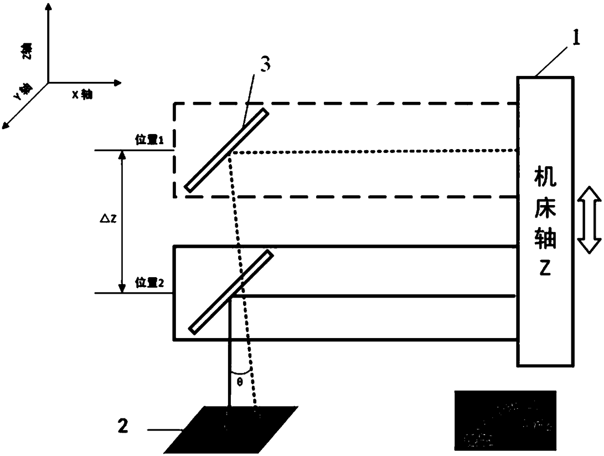
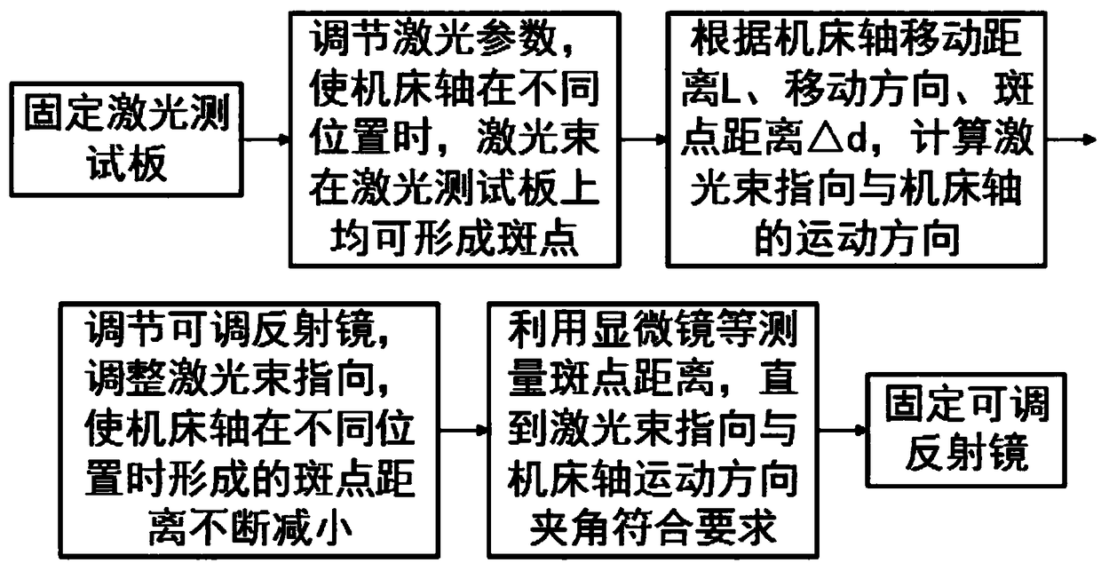
[0030] like figure 1 As shown, the inventive method drives the adjustable reflector to move through the machine tool shaft, and the laser beam passing through the reflector 3 forms spots on the fixed laser test board 2, and judges the relationship between the laser beam and The included angle of the movement direction of the machine tool axis is used to adjust the angle of the adjustable mirror to adjust the laser pointing. In addition, the above method can also be used to measure the position of the spot formed by the laser beam on the laser test board when the machine tool shaft is at different positions with the help of a high-magnification microscope, so that the adjustment of the laser beam is more accurate, and the direction of the laser beam and the machine tool shaft can be adjusted. parallel purpose. Therefore, the meth...


PUM

PropertyMeasurementUnit
diameteraaaaaaaaaa

Abstract

The invention relates to a laser beam and machine tool shaft moving direction parallelism adjusting method. The problems that an existing laser beam pointing direction adjusting method is high in costand tedious in the adjusting process are solved. The adjusting method comprises the following steps that 1) a test plate is fixed; 2) measuring spots are formed; 3) the adjusting angle of a reflectoris obtained; 4) the reflector is adjusted; 5) the step 2) to the step 4) are repeated; and 6) the reflector is fixed.

Description

technical field [0001] The invention relates to a method for adjusting laser precision, in particular to a method for adjusting the parallelism between a laser beam and the movement direction of a machine tool axis. Background technique [0002] In the process of laser processing, the laser emits a laser beam with high power density, which transfers the energy to the area to be processed, so as to realize the removal of material and the processing of parts. Because laser processing has the advantages of small heat-affected area, processing is not limited by the mechanical properties of materials, there is no tool wear, and there is no processing stress during processing, it has been widely used in hard and brittle materials, difficult-to-machine metals and thin-walled parts. processing. In laser processing equipment, the pointing accuracy of the laser beam determines the position accuracy of the final laser focus, which directly affects the processing accuracy of the parts ...

Claims


Application Information

Patent Timeline
Patent Type & Authority Applications(China)
IPC IPC(8): B23K26/70
CPCB23K26/702
Inventor 李晨晨谭羽李珣李明
Owner XI'AN INST OF OPTICS & FINE MECHANICS - CHINESE ACAD OF SCI
Why Eureka
Try Eureka