T-pipe welding robot

A welding robot and three-way pipe technology, which is applied in welding equipment, auxiliary welding equipment, welding/cutting auxiliary equipment, etc., can solve the problems of feeding, inability to process three-way pipes, and inability to adjust the angle of branch pipe fixtures, and is widely applicable. The effect of high stability, fast processing speed, and easy welding

Active Publication Date: 2019-01-11
ZHIMAIDE CO LTD
View PDF7 Cites 15 Cited by
  • Summary
  • Abstract
  • Description
  • Claims
  • Application Information

AI Technical Summary

Problems solved by technology

[0002] Metal tee pipes are generally produced in the form of welding. When welding a general tee pipe, the main pipe is clamped by the main pipe clamp, the branch pipe is clamped by the branch pipe clamp, and the branch pipe is moved to the main pipe by the cylinder drive. The branch pipes are welded to connect the two fixedly, but the feeding of the branch pipes of the existing tee pipe welding device needs to be manually loaded, and the angle of the branch pipe clamps cannot be adjusted, which leads to the failure of the main pipe and branch pipes of the processed tee pipe. The angle between them is fixed, but the angle between the branch pipe and the main pipe of some existing tee pipes is different, which makes the tee pipe welding device unable to process a variety of tee pipes with different angles between the main pipe and the branch pipe, making the tee The scope of application of the pipe welding device is small

Method used


Image

  • T-pipe welding robot
  • T-pipe welding robot
  • T-pipe welding robot

Examples


Embodiment Construction

[0032] The following will be combined with Figure 1 to Figure 12 The present invention is described in detail, and the technical solutions in the embodiments of the present invention are clearly and completely described. Apparently, the described embodiments are only some of the embodiments of the present invention, not all of them. Based on the embodiments of the present invention, all other embodiments obtained by persons of ordinary skill in the art without making creative efforts belong to the protection scope of the present invention.

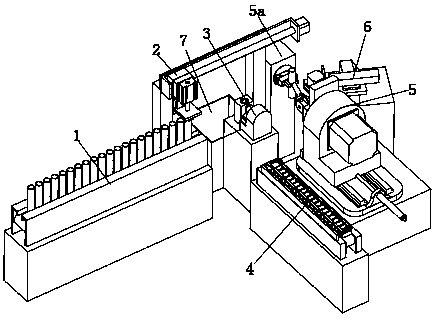
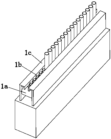
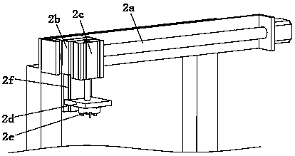
[0033] The present invention provides a kind of tee pipe welding robot here through improvement, as Figure 1-Figure 12As shown, it includes a main feeding mechanism 1, a transfer mechanism 2, a stamping mechanism 3, a branch pipe feeding mechanism 4, a positioning mechanism 5 and a laser welding device 6, and the punching mechanism 3 is located at the end of the main feeding mechanism 1. The transfer mechanism 2 is installed above the m...


PUM


Abstract

The invention relates to the field of T-pipe machining, in particular to a T-pipe welding robot. The T-pipe welding robot comprises a main pipe feeding mechanism, a transferring mechanism, a punchingmechanism, a branched pipe feeding mechanism, a positioning mechanism and a laser welding device. The punching mechanism is located at the tail end of the main pipe feeding mechanism. The transferringmechanism is mounted above the main pipe feeding mechanism and the punching mechanism. The positioning mechanism is located below the tail end of the transferring mechanism. The branched pipe feedingmechanism and the laser welding mechanism are separately located on the two sides of the positioning mechanism. The positioning mechanism comprises a main pipe clamping assembly, a first three-jaw chuck, an adjustment assembly, a driving assembly and a rotating assembly, wherein the driving assembly is mounted at the upper end of the rotating assembly, the adjustment assembly is mounted at one end of the driving assembly, and the first three-jaw chuck is mounted on the adjustment assembly. The T-pipe welding robot has the beneficial effects that welding of T-pipes can be automatically completed, and human-assisted feeding is not needed; and meanwhile, the T-pipe welding robot is suitable for welding branched pipes and main pipes with different included angles therebetween.

Description

technical field [0001] The invention relates to the field of welding processing, in particular to a three-way pipe welding robot. Background technique [0002] Metal tee pipes are generally produced in the form of welding. When welding a general tee pipe, the main pipe is clamped by the main pipe clamp, the branch pipe is clamped by the branch pipe clamp, and the branch pipe is moved to the main pipe by the cylinder drive. The branch pipes are welded to connect the two fixedly, but the feeding of the branch pipes of the existing tee pipe welding device needs to be manually loaded, and the angle of the branch pipe clamps cannot be adjusted, which leads to the failure of the main pipe and branch pipes of the processed tee pipe. The angle between them is fixed, but the angle between the branch pipe and the main pipe of some existing tee pipes is different, which makes the tee pipe welding device unable to process a variety of tee pipes with different angles between the main pip...

Claims


Application Information

Patent Timeline
Patent Type & Authority Applications(China)
IPC IPC(8): B23K37/053B23K37/04B23K37/02
CPCB23K37/0247B23K37/0435B23K37/0533
Inventor 夏明爱
Owner ZHIMAIDE CO LTD
Why Eureka
Try Eureka