
Oilstone clamping and feeding device for roller lapping machine

A technology of feeding device and lapping machine, which is applied in the direction of grinding drive device, grinding machine parts, working carrier, etc., can solve the problems of increased production cost, low product yield, and broken oilstone, and achieves improved grip. The effect of maintaining stability, convenient and quick operation, and reducing the width of waste

Pending Publication Date: 2019-01-11
洛阳万有力科技有限公司
View PDF7 Cites 4 Cited by
  • Summary
  • Abstract
  • Description
  • Claims
  • Application Information

AI Technical Summary

Problems solved by technology

[0003] This kind of clamping mechanism has the following problems in the use process: 1. The clamping mechanism must ensure the clamping strength for the oil stone, and the contact point between the screw and the oil stone must be properly close to the middle of the oil stone, so that the utilization rate in the width direction of the oil stone is low. Low, serious waste; 2. The clamping method through screw point contact is easy to cause the instability of the oilstone in the roller grinding process due to the different tightening degrees of two or more screws, resulting in a low product yield; 3 1. The clamping method of screw point contact is easy to cause the whetstone to break due to the over-tightening of the screw, which increases the production cost; 4. To replace the whetstone, you need to loosen all the screws first, and then re-tighten all the screws after replacing the whetstone. It needs to be kept uniform, resulting in a long and difficult time for oil stone replacement and clamping, which is not conducive to the improvement of enterprise production efficiency

Method used


Image

  • Oilstone clamping and feeding device for roller lapping machine
  • Oilstone clamping and feeding device for roller lapping machine
  • Oilstone clamping and feeding device for roller lapping machine

Examples


Embodiment Construction

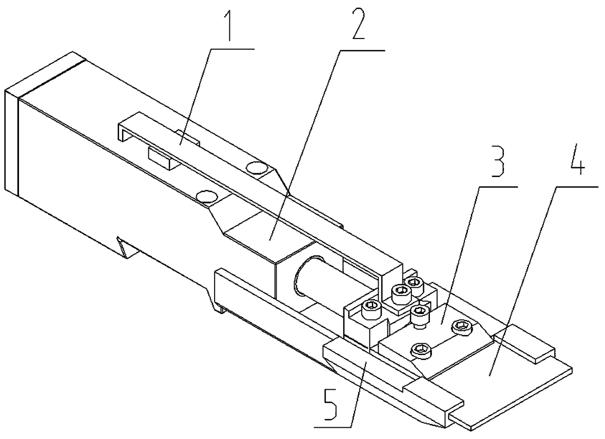
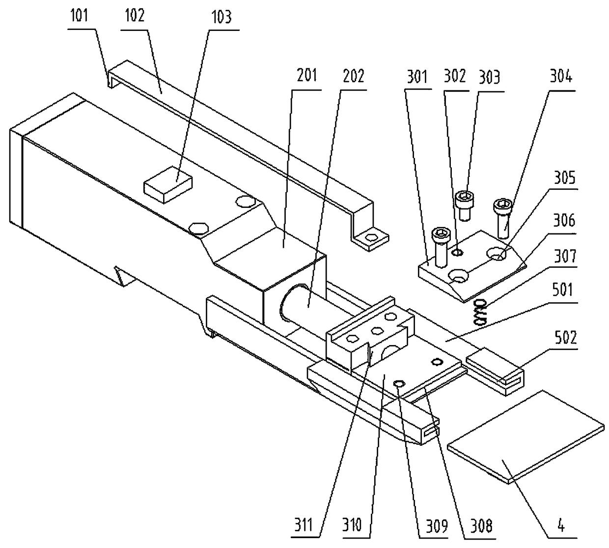
[0024] Such as figure 1 and figure 2 As shown, a whetstone 4 clamping and feeding device for a roller lapping machine of the present invention includes a constant pressure feeding mechanism 2 . The constant pressure feeding mechanism 2 may include a cylinder body 201 and a piston rod 202 pierced in the cylinder body 201, and the piston rod 202 may continue to extend toward an oil cylinder, an air cylinder, an electric push rod protruding from the cylinder body 201 with a constant pressure or other components with similar functions. The piston rod 202 is provided with a fixing clip 3 for clamping and fixing the oil stone 4 , and the cylinder body 201 is provided with a guide seat 5 for feeding the oil stone 4 along with the piston rod 202 . Through the constant pressure feed mechanism 2, the grinding oil stone 4 can be pressed against the roller to be ground, and the oil stone 4 can be pushed forward after the oil stone 4 is worn, so as to ensure a constant pressure during t...


PUM


Abstract

The invention relates to the field of precision roller processing equipment, in particular to an oilstone clamping and feeding device for a roller lapping machine. The oilstone clamping and feeding device comprises a constant-pressure feeding mechanism, a fixing clamp arranged on a piston rod of the constant-pressure feeding mechanism and a guide seat arranged on a cylinder body. The fixing clampcomprises a first clamping plate connected to the piston rod and a second clamping plate connected to the first clamping plate. Penetrating holes are formed in the position, close to a clamping part,of the second clamping plate. Fulcrum screws penetrate the penetrating holes. The small ends of the fulcrum screws are installed in first threaded holes formed in the first clamping plate, and a second threaded hole is formed in the side where the penetrating holes are opposite to the clamping part of the second clamping plate. A tightening screw is cooperatively installed in the second threaded hole, and the small end of the tightening screw can penetrate the second threaded hole and be in contact with the first clamping plate. By the adoption of the oilstone clamping and feeding device, theutilization rate of the oilstone can be increased, the stability of the oilstone in the grinding process is maintained, clamping is convenient, the production efficiency and the finished product rateof enterprises are increased, and the production cost is reduced.

Description

technical field [0001] The invention relates to the field of precision roller processing equipment, in particular to an oilstone clamping and feeding device used for a roller lapping machine. Background technique [0002] During the grinding process of precision bearing rollers, the held oil stone is usually clamped on the lapping machine, and then the continuous rollers to be processed are controlled to rotate at high speed and move along the length of the oil stone to complete the roller lapping. The clamping mechanism of the whetstone in the prior art generally includes a splint, two or more nuts fixed on the lapping machine above the splint, and screws fitted in the nuts respectively. After placing the oil stone on the splint, tighten the side of the oil stone against the splint by screwing the screw closer to the splint so that the small end of the screw pushes one side of the oil stone tightly against the splint. [0003] This kind of clamping mechanism has the follow...

Claims


Application Information

Patent Timeline
Patent Type & Authority Applications(China)
IPC IPC(8): B24B37/27B24B47/20
CPCB24B37/27B24B47/20Y02P70/10
Inventor 杨建武张志成
Owner 洛阳万有力科技有限公司
Features
  • Generate Ideas
  • Intellectual Property
  • Life Sciences
  • Materials
  • Tech Scout
  • Unparalleled Data Quality
  • Higher Quality Content
  • 60% Fewer Hallucinations
Learn More