A four-roller spindle device for a multi-wire cutting machine

A technology of multi-wire cutting machine and spindle device, which is applied to fine working devices, manufacturing tools, stone processing equipment, etc., can solve the problems of reduced cutting accuracy, increased thermal deformation of the main roller, and reduced cutting efficiency, achieving rigidity and Improved stability, reduced spindle distance, and reduced consumable costs

Active Publication Date: 2019-08-09
HUNAN YUJING MACHINE
View PDF8 Cites 0 Cited by
  • Summary
  • Abstract
  • Description
  • Claims
  • Application Information

AI Technical Summary

Problems solved by technology

[0005] The diamond wire multi-wire cutting machine and wafer slicer have the following disadvantages: when cutting at high speed, the traditional main roll is used, and the thermal deformation of the main roll increases accordingly, resulting in a decrease in cutting accuracy, a decrease in the quality of the finished product, and easily causing breakage. The auxiliary roller is fixed. Since the loss of the coating layer of the auxiliary roller is much greater than that of the main roller, the initial tension of the diamond wire decreases with the increase in the number of cuts, and the cutting efficiency is greatly reduced and affects the quality of the slice.

Method used


Image

  • A four-roller spindle device for a multi-wire cutting machine
  • A four-roller spindle device for a multi-wire cutting machine
  • A four-roller spindle device for a multi-wire cutting machine

Examples


Embodiment

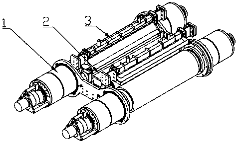
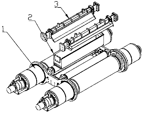
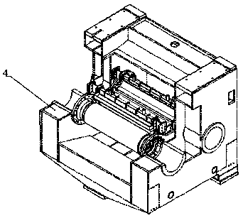
[0030]Referring to the accompanying drawings, a four-roller spindle device of a multi-wire cutting machine includes a spindle system 1, a material receiving box assembly 2 and a nozzle assembly 3, and the spindle system 1 and the nozzle assembly 3 are installed in the cutting chamber 4 of the multi-wire cutting machine Above, the spindle system 1 includes 2 sets of main roller assemblies 1-1, 2 sets of auxiliary roller assemblies 1-2, a front mounting bracket 1-3 and a rear mounting bracket 1-4, and the 2 sets of main roller assemblies 1-1 Symmetrically installed on the front mounting bracket 1-3 and the rear mounting bracket 1-4, the two sets of secondary roller assemblies 1-2 are symmetrically installed on the front mounting bracket 1-3 and the rear mounting bracket 1-4, and are located in two groups In the middle of the main roller assembly 1-1, the material receiving box assembly 2 is installed in the limit groove of the front mounting bracket 1-3 and the rear mounting brac...


PUM


Abstract

A four-roller main shaft device of a multi-wire cutting machine comprises a main shaft system, a material receiving box assembly and a nozzle assembly. The main shaft system and the nozzle assembly are arranged on a cutting chamber. The main shaft system comprises two main roller assemblies, two auxiliary roller assemblies, a front installing support and a rear installing support. The two main roller assemblies are symmetrically arranged on the front installing support and the rear installing support. The two auxiliary roller assemblies are symmetrically arranged on the front installing support and the rear installing support and located between the main roller assemblies. The material receiving box assembly is arranged in limiting grooves of the front installing support and the rear installing support and located between the auxiliary roller assemblies. Each main roller assembly comprises a rotation water cooling device, a driven bearing box, a main roller, a driving bearing box and ahollow locking screw. Each auxiliary roller assembly comprises an auxiliary roller, a bearing block I, a bearing II, a locking nut I, a sealing cover I, a bearing block II, a bearing III, a locking nut II, a sealing cover II, an installing frame, an adjusting screw and a nut. By utilization of the four-roller main shaft device, the requirements for high-speed and high-precision cutting of diamondwires can be met.

Description

technical field [0001] The invention relates to a four-roller main shaft device of a multi-wire cutting machine suitable for diamond wire cutting technology. Background technique [0002] At present, traditional multi-wire cutting machines for solar silicon wafers (for example: Swiss DS264 / Japanese PV800, NTC442) mostly use mortar line and suspension cutting methods, and their disadvantages are: 1. The cutting method can only use mortar line cutting, and the line speed is 800-900m / min, the single-knife slicing time of the mortar line is about 8-10 hours, and the cutting efficiency is low; 2. The single-piece line consumption of the mortar line is about 150m, and the single-piece line consumption is too large; 3. The mortar line cutting method is in the cutting Mortar needs to be prepared before, and waste mortar needs to be disposed of after cutting, which is cumbersome and not environmentally friendly; 4. The distance between the main rollers is large, and large wire bows a...

Claims


Application Information

Patent Timeline
Patent Type & Authority Patents(China)
IPC IPC(8): B28D5/04B28D7/02
CPCB28D5/0058B28D5/0076B28D5/045
Inventor 戴瑜兴杨佳葳匡腾芳邱宇俊
Owner HUNAN YUJING MACHINE
Why Eureka
Try Eureka