Eureka AIR delivers breakthrough ideas for toughest innovation challenges, trusted by R&D personnel around the world.

Discharging shifting device of feeding machine for brake calipers of brake pumps

A technology of shifting device and brake caliper is applied in the field of unloading shifting device of brake pump brake caliper feeding machine, which can solve the problems of inaccurate conveying position of manual operation, high labor intensity of manual operation, low work efficiency, etc. , to achieve the effect of compact structure, high work efficiency and convenient operation

Inactive Publication Date: 2019-01-11
SUZHOU GUANHAOSI PRECISION MACHINERY CO LTD
View PDF0 Cites 0 Cited by
  • Summary
  • Abstract
  • Description
  • Claims
  • Application Information

AI Technical Summary

Problems solved by technology

[0002] At present, the trend of automation is becoming more and more obvious. A good mechanism design can improve production efficiency and reduce production costs. The brake pump is composed of brake calipers, spark plugs, rubber rings and other components. Brake calipers are one of the essential parts of the brake pump. In the process of feeding the brake caliper, a shifting device is usually required. At present, shifting usually requires manual operation, which is labor-intensive, inefficient, time-consuming, and labor-intensive. Moreover, the manual operation is often inaccurate in the delivery position, which directly affects the The operation of the next process, in view of this, it is necessary to improve the blanking and shifting device of the existing brake pump brake caliper feeder

Method used


Image

  • Discharging shifting device of feeding machine for brake calipers of brake pumps
  • Discharging shifting device of feeding machine for brake calipers of brake pumps

Examples


Embodiment Construction

[0008] The preferred embodiments of the present invention will be described in detail below in conjunction with the accompanying drawings, so that the advantages and features of the invention can be more easily understood by those skilled in the art, so as to define the protection scope of the present invention more clearly.

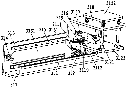
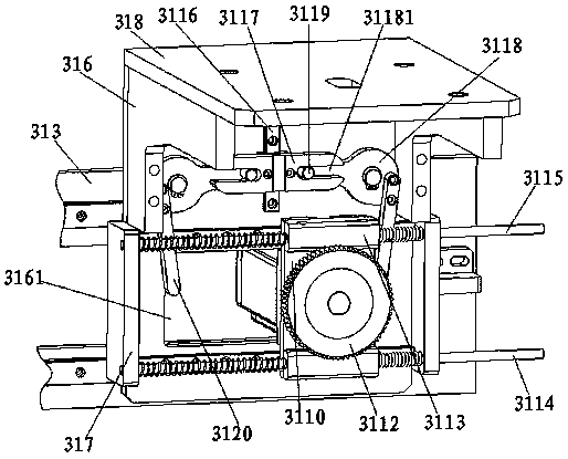
[0009] see figure 1 and figure 2 , the embodiment of the present invention includes:

[0010] A blanking and shifting device of a brake pump brake caliper loading machine, the blanking and shifting device of the brake pump brake caliper loading machine includes a shift mounting plate 311, the upper end surface of the shift mounting plate 311 passes through the The shift rack spacer is fixed with a blanking shift rack 312, and a shift vertical plate 313 is also fixed on the installation frame 1, the lower end surface of the shift vertical plate 313 is fixed with the upper end face of the shift mounting plate 311, and the shift Both ends of the front of...


PUM


Abstract

The invention discloses a discharging shifting device of a feeding machine for brake calipers of brake pumps. The discharging shifting device of the feeding machine for the brake calipers of the brakepumps comprises a shifting installation plate. A discharging shifting rack is fixed to the upper end face of the shifting installation plate through a discharging shifting rack cushion block. A shifting vertical plate is fixed to an installation machine frame. The lower end face of the shifting vertical plate is fixed to the upper end face of the shifting installation plate. Limiting blocks are fixed to the two ends of the front side of the shifting vertical plate. A motor shifting through groove is arranged between the two limiting blocks of the shifting vertical plate. First discharging shifting guide rails are fixed to the front side of the shifting vertical plate and are located on the upper portion and the lower portion of the motor shifting through groove. The two first dischargingshifting guide rails are parallel to the discharging shifting rack, and a discharging shifting plate is fixed to the sliding blocks of the two first discharging shifting guide rails. A shifting receding through groove is formed in the position, corresponding to the motor shifting through groove, of the discharging shifting plate. In this way, the discharging shifting device can move conveniently and is high in efficiency and low in production cost.

Description

technical field [0001] The invention relates to the field of mechanical automation, in particular to a material unloading and shifting device for a brake pump brake caliper loader. Background technique [0002] At present, the trend of automation is becoming more and more obvious. A good mechanism design can improve production efficiency and reduce production costs. The brake pump is composed of brake calipers, spark plugs, rubber rings and other components. Brake calipers are one of the essential parts of the brake pump. In the process of feeding the brake caliper, a shifting device is usually required. At present, shifting usually requires manual operation, which is labor-intensive, inefficient, time-consuming, and labor-intensive. Moreover, the manual operation is often inaccurate in the delivery position, which directly affects the In view of this, it is necessary to improve the blanking and shifting device of the existing brake pump brake caliper feeding machine for the...

Claims


Application Information

Patent Timeline
Patent Type & Authority Applications(China)
IPC IPC(8): B65G47/04
CPCB65G47/04B65G2201/02
Inventor 鲍敏辉
Owner SUZHOU GUANHAOSI PRECISION MACHINERY CO LTD
Why Eureka
Eureka Blog
Learn More