Embroidery machine and embroidery machine cloth fixing device

A fixing device and technology for embroidery machines, applied in the field of embroidery machines, can solve the problems of long consumption time and painful palms, and achieve the effects of speeding up production efficiency, reducing labor intensity, and facilitating material loading and placement.

Active Publication Date: 2019-01-11
徐剑清
View PDF8 Cites 2 Cited by
  • Summary
  • Abstract
  • Description
  • Claims
  • Application Information

AI Technical Summary

Problems solved by technology

Faster embroidery workers need more than 10 minutes to finish at the fastest, and the number of clamping and unloading clips 17 in the workload of a shift reaches about 8,000 times, which consumes a long time, and requires workers to use the palm of their hands when clamping the cloth. Knocking down a cloth clip 17 will cause pain to the palm, which has great requirements on the labor intensity of the embroidery workers.

Method used


Image

  • Embroidery machine and embroidery machine cloth fixing device
  • Embroidery machine and embroidery machine cloth fixing device
  • Embroidery machine and embroidery machine cloth fixing device

Examples


Embodiment 1

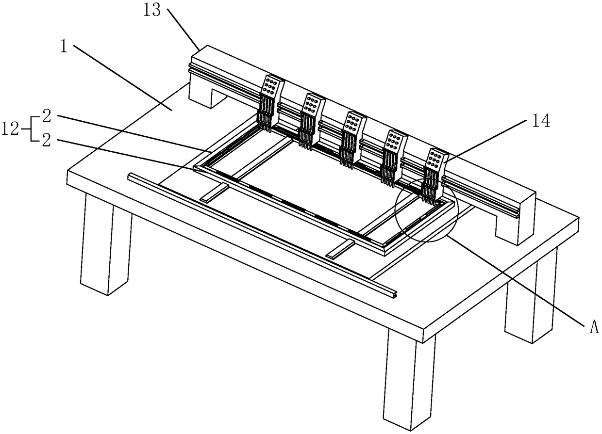
[0039]Embodiment 1: An embroidery machine, including an embroidery machine cloth fixing device.

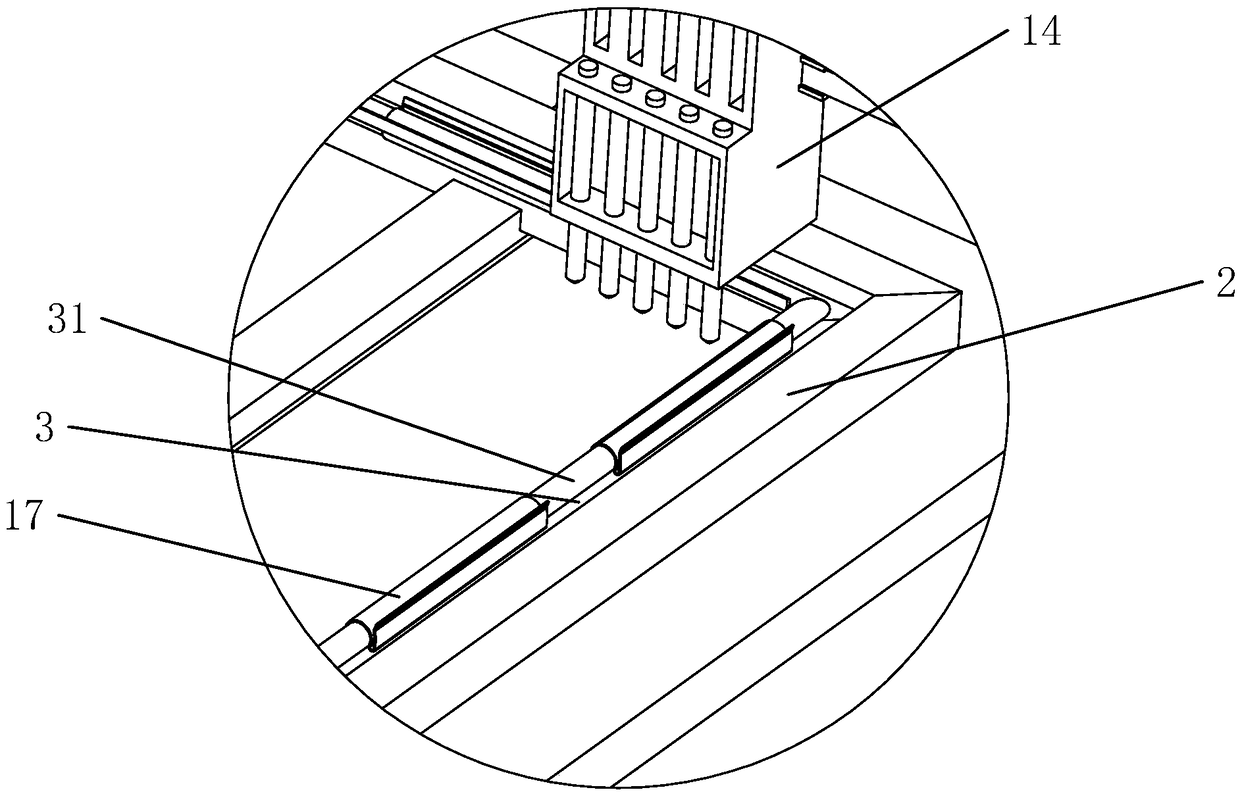
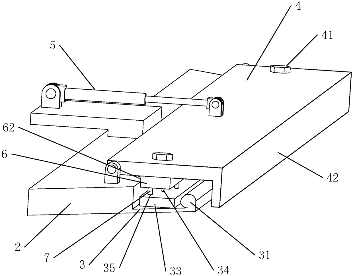
[0040] An embroidery machine cloth fixing device, such as image 3 and Figure 4 As shown, it includes a fixing groove 3, a pressing plate 4 and a driving mechanism 5. The fixing groove 3 is opened on the fixing frame 2 of the embroidery machine, and is located at the edges of the four fixing frames 2 close to the center of the fabric. The fixing groove 3 is along the edge of the fixing frame 2. The length direction extends, and the adjacent fixing grooves 3 are vertical in pairs and communicate with each other.

[0041] Such as image 3 and Figure 4 As shown, the pressing plate 4 is hinged on the fixing frame 2 and can rotate around the hinge so as to realize two states of opening and pressing the fixing groove 3 .

[0042] Such as image 3 and Figure 4 As shown, the edge of the fixing groove 3 close to the center of the cloth is integrally provided with a convex strip 31...

Embodiment 2

[0052] Embodiment 2: The difference between embodiment 2 and embodiment 1 is that the connection mode between the pressing pin 7 and the pressing bar 6 is different, such as Figure 7 As shown, in the embodiment 2, the pressing pin 7 and the pressing bar 6 are integrally formed, which can save a lot of manufacturing cost.


PUM


Abstract

The invention relates to the technical field of embroidery machines, and discloses an embroidery machine and an embroidery machine cloth fixing device. The embroidery machine cloth fixing device comprises a fixing groove arranged in a fixed frame and extending along the length direction of the fixed frame, a pressing plate arranged on the fixed frame and a driving mechanism for driving the pressing plate to make the pressing plate press the fixed groove. The driving mechanism is used to drive the pressing plate to rotate or move up and down in order to realize the opening and closing of the pressing plate, and the edge of the cloth is pressed between the fixing groove and the pressing plate when the pressing plate is closed, so troubles brought by fixation of the cloth through using a lotof cloth clips by embroidery workers' hands are reduced, and the labor intensity is reduced.

Description

technical field [0001] The invention relates to an embroidery machine and a cloth fixing device for the embroidery machine, belonging to the technical field of embroidery machines. Background technique [0002] China's embroidery machine industry began in the late 1990s and has begun to take shape after nearly 30 years of development. In recent years, it has been developing in the more difficult direction of super long and super long. [0003] Such as figure 1 Shown, existing embroidery machine comprises frame 11, is arranged on the embroidery frame 12 on frame 11, is arranged on frame 11 and is provided with fixed beam 13 along the length direction of frame 11 and several is arranged on fixed beam 13 And the embroidery head 14 distributed along the length direction of the fixed beam 13, the embroidery frame 12 is arranged on the frame 11 by sliding along the X-axis direction by the X-axis motor arranged on the frame 11, and the embroidery frame 12 is arranged on the frame...

Claims


Application Information

Patent Timeline
Patent Type & Authority Applications(China)
IPC IPC(8): D05C9/00
CPCD05C9/00
Inventor 徐剑清
Owner 徐剑清
Why Eureka
Try Eureka