A road marking machine

A technology for marking machines and roads, which is applied in the direction of roads, roads, road repairs, etc. It can solve the problems of reducing the use effect of marking machines, poor pigment grinding and dispersion, and high density of pigments and fillers, achieving low pressure and small tension , the effect of high transmission power

Active Publication Date: 2020-11-24
四川志德公路工程有限责任公司
View PDF12 Cites 1 Cited by
  • Summary
  • Abstract
  • Description
  • Claims
  • Application Information

AI Technical Summary

Problems solved by technology

[0004] But its disadvantage is that when the workload of the marking line is large or the pigments used in the paint are not ground finely, poorly dispersed, the pigment-base ratio is too large, the density of pigments and fillers is high, etc., the paint will be precipitated in the tank. The paint will agglomerate, which will block the discharge port and reduce the use effect of the marking machine

Method used


Image

  • A road marking machine
  • A road marking machine
  • A road marking machine

Examples


Embodiment Construction

[0032] The present invention will be described in further detail below in conjunction with the accompanying drawings.

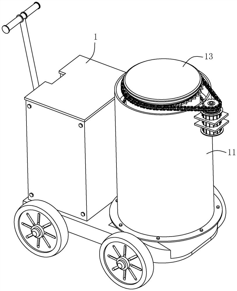
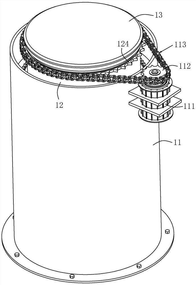
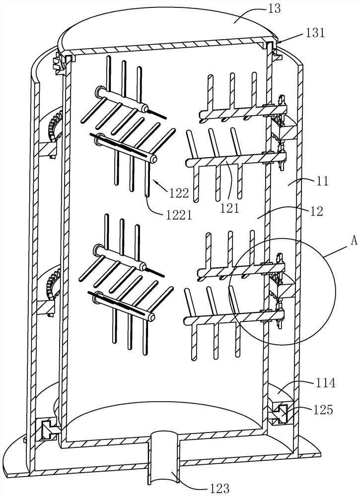
[0033] combine figure 1 and figure 2 , is a road marking machine disclosed in the present invention, comprising a machine body 1 on which a hopper 11 is arranged.

[0034] combine figure 2 and image 3 A mixing bucket 12 is arranged coaxially with the hopper 11 in the hopper 11, a chute 114 is arranged on the inner wall of the hopper 11 along the inner wall of the hopper 11, and the chute 114 is located on the hopper 11 near the bottom wall of the hopper 11. A slider 125 slidably connected in the sliding groove 114 is provided on the top.

[0035] Such as image 3 As shown, in this embodiment, the cross section of the chute 114 is set in a "T" shape, and the slider 125 is arranged in cooperation with the "T"-shaped chute 114, and the "T"-shaped chute 114 and the slider 125 are paired The rotation of the mixing bucket 12 in the hopper 11 has a better g...


PUM


Abstract

The invention relates to a highway marking machine, belonging to the technical field of highway engineering machinery, including a body, wherein a hopper is arranged on the body; a stirring bucket isarranged coaxially with the hopper in the hopper, and is rotatably connected with the hopper; the upper part of the hopper and the stirring bucket are provided with openings; a stirring device is arranged in the stirring bucket, and the stirring device comprises a plurality of sets of stirring members arranged along the height direction of the stirring bucket; each set of stirring members includesa plurality of stirring shafts circumferentially and uniformly distributed on the stirring bucket; a plurality of stirring blades are arranged on the stirring shaft along the length direction of thestirring shaft in the stirring bucket; a plurality of agitating shafts in each set of agitating members are located at the same height; the driving member drives the stirring bucket to rotate in the hopper, and the bottom wall center of the stirring bucket is communicated with a discharge pipe which is arranged through the hopper and extends to the outside of the hopper; and the driving member drives the stirring bucket to rotate in the hopper, so that the stirring blades have the stirring effect on the paint, thereby preventing the paint in the stirring bucket from precipitating or agglomerating.

Description

technical field [0001] The invention relates to the technical field of road engineering machinery and equipment, in particular to a road marking machine. Background technique [0002] Marking machine, a road construction machine that is widely used in roads, high-grade highways, parking lots, squares and runways to draw different restrictions, guidelines and warnings on the flat ground. With its fast, efficient, accurate and other advantages, the marking machine has played a huge role in urban planning and road construction, saving the construction period and economic investment of road construction to the greatest extent. [0003] The Chinese patent with the authorized notification number CN205399172U discloses a road marking machine, which includes a tank body. 1. The front and rear ends of the bottom of the tank body are respectively rotated and fixed with horizontal rotating shafts through the support rods. Wheels are fixed at both ends of the rotating shaft. The middle...

Claims


Application Information

Patent Timeline
Patent Type & Authority Patents(China)
IPC IPC(8): E01C23/20
CPCE01C23/20
Inventor 张野陈志强徐永兴邓猛周乐祥
Owner 四川志德公路工程有限责任公司
Why Eureka
Try Eureka