
Mobile mortar production equipment for building and production method thereof

A technology for production equipment and construction, which is applied to mobile mortar production equipment for construction and its production field, can solve problems such as uneven mixing, poor mixing effect, and impact on production quality, and achieves improved practicability, reduced resistance, and improved reliability. and practical effects

Inactive Publication Date: 2020-12-04
武汉德创天成科技发展有限公司
View PDF10 Cites 1 Cited by
  • Summary
  • Abstract
  • Description
  • Claims
  • Application Information

AI Technical Summary

Problems solved by technology

The mortar stirring device in the above-mentioned patent has the following disadvantages: although the device provides a certain stirring function, the stirring effect is poor, which may cause uneven mixing and affect the production quality

Method used


Image

  • Mobile mortar production equipment for building and production method thereof
  • Mobile mortar production equipment for building and production method thereof
  • Mobile mortar production equipment for building and production method thereof

Examples


Embodiment 1

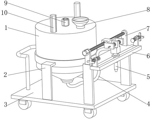
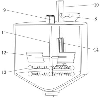
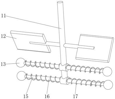
[0037] A mobile mortar production equipment for construction, such as Figure 1-5 As shown, it includes a stirring tank 1 and a car body 3, the top of the stirring tank 1 is welded with a feed hopper 8, the stirring tank 1 is installed on the outer wall of the top of the car body 3 through the mounting seat 2, and the outer wall of the top of the stirring tank 1 is fixed by screws There are two symmetrical electric telescopic rods 10, the output ends of the two electric telescopic rods 10 are rotatably connected to a rotating seat 22, and the outer wall of the rotating seat 22 is rotatably connected to a lifting frame 14, and the outer wall of the lifting frame 14 is provided with evenly distributed rectangular passages 18 , the outer wall of the bottom end of the lifting frame 14 is fixed with a bowl-shaped seat 19 by screws; a stirring mechanism is arranged between the two lifting frames 14, and the stirring mechanism includes a stirring main shaft 11 and more than two stirri...

Embodiment 2

[0046] A production method of the mobile mortar production equipment described in embodiment 1, such as Figure 1-5 shown, including the following steps:

[0047] S1: Weighing mortar raw materials;

[0048] S2: Add the mortar raw material into the mixing tank 1 through the feed hopper 8;

[0049] S3: Control the stirring motor 9 to rotate and stir the mortar;

[0050] S4: Control the electric telescopic rod 10 to work to vertically stir the mortar;

[0051] S5: After the stirring is completed, the stirring motor 9 and the electric telescopic rod 10 are stopped, and the mortar is output through the pump body.


PUM


Abstract

The invention discloses mobile mortar production equipment for a building and a production method thereof, relates to the technical field of mortar production equipment and aims at improving the stirring effect. The equipment comprises an agitator tank and a vehicle body, wherein a feed hopper is welded to the top of the agitator tank; the agitator tank is arranged on the outer wall of the top ofthe vehicle body through a mounting seat; and two symmetrical electric telescopic rods are fixed to the outer wall of the top of the agitator tank through screws. The application method of the equipment comprises the following steps of weighing mortar raw materials; adding the mortar raw materials into the agitator tank through the feed hopper; and controlling an agitator motor to work to rotatably stir the mortar. Through the arrangement of lifting frames, the electric telescopic rods and other structures, the electric telescopic rods can be used for driving the lifting frames to do verticalreciprocating motion, and a bowl-shaped seat ascends and descends along with the lifting frames; the resistance can be reduced due to the fact that the bottom of the bowl-shaped seat has radian; and the bowl-shaped seat is of a bowl-shaped structure and can drive bottom mortar to ascend during ascending, so that the special shape of the bowl-shaped seat is used for stirring the mortar.

Description

technical field [0001] The invention relates to the technical field of mortar production equipment, in particular to a mobile mortar production equipment for construction and a production method thereof. Background technique [0002] Mortar is a bonding substance used in building bricks. It is composed of a certain proportion of sand and cementing materials and water. During the preparation of mortar, various stirring devices are often used to fully mix the raw materials. Because the mortar is relatively viscous, The general stirring device only stirs through the stirring blade, and the stirring effect is poor, resulting in uneven mixing and affecting the production quality. [0003] After searching, the Chinese patent application number is CN201922011787.2, which discloses a mortar mixing device, which seals the mixing tank through the shell, prevents the mortar from splashing and ensures the temperature around the mixing tank, and controls the shaft sleeve group through th...

Claims


Application Information

Patent Timeline
IPC IPC(8): B28C5/16B28C5/08E04G21/04
CPCB28C5/0806B28C5/0856B28C5/16E04G21/04E04G2021/049
Inventor 陈晓勤
Owner 武汉德创天成科技发展有限公司
Learn More