Oilfield electric water injection tool stroke sensor

A travel sensor, sensor body technology, applied in the production of fluids, wellbore/well components, earthwork drilling and other directions, can solve the problems of inability to directly install and use, the structure cannot be matched, etc., to improve the level of automatic control and the accuracy of work The effect of high degree, simple structure and easy installation

Pending Publication Date: 2019-01-11
SHENZHEN JIAYUNTONG ELECTRONICS
0 Cites 1 Cited by

AI-Extracted Technical Summary

Problems solved by technology

In the prior art, there is also a travel sensor in the form of torsion, and its structure cannot ma...

Method used

[0019] To achieve this goal, the present invention includes a sensor body 1, the sensor body 1 is an upper end surface is provided with a window 11 of the cuboid structure of the housing, this structure of the housing, more convenient to install. A lead screw transmission device is arranged in the sensor body, the lead screw 2 of the lead screw drive device protrudes from the sensor body 1, and a driven gear 4 is a...

Abstract

The invention relates to an oilfield electric water injection tool stroke sensor and belongs to the technical field of the stroke control and valve position feedback control of a water distribution valve in an oilfield water injection tool. The oilfield electric water injection tool stroke sensor is characterized in that the sensor comprises a sensor body which is a shell with a rectangular structure, an upper end surface of the sensor body is provided with a window, a screw driving device is arranged in the sensor body, a screw of the screw driving device extends out of the sensor body, the screw extending out of the sensor body is provided with a driven gear which engages with a driving gear on an oilfield electric water injection tool. An upper end surface of the sensor body is providedwith a stroke sensor circuit board which is connected to a power supply through a wire. The oilfield electric water injection tool stroke sensor has the advantages of simple structure and easy installation, the sensor is used with the oilfield electric water injection tool to accurately provide the stroke control and valve position feedback control of the water distribution valve in the oilfieldwater injection tool, and the automatic control level and precision of the working of the oilfield electric water injection tool are improved.

Application Domain

Technology Topic

Image

  • Oilfield electric water injection tool stroke sensor
  • Oilfield electric water injection tool stroke sensor
  • Oilfield electric water injection tool stroke sensor

Examples

  • Experimental program(1)

Example Embodiment

[0017] Combine below figure 1 , figure 2 , image 3 with Figure 4 , To further explain the present invention:
[0018] Because all the stroke sensors in the prior art cannot be used on the existing oilfield electric water injection tools due to structural reasons, the focus of the invention is to conveniently install the stroke sensor on the oilfield electric water injection tool stroke sensor, and can Realize accurate stroke control and valve position feedback of water distribution valves in oilfield water injection tools.
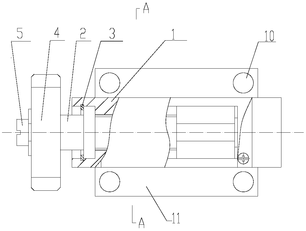
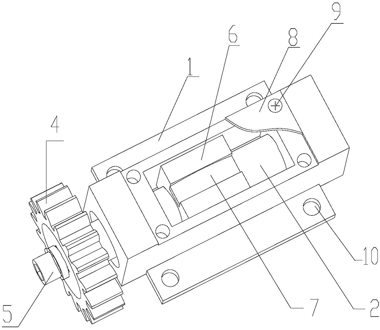
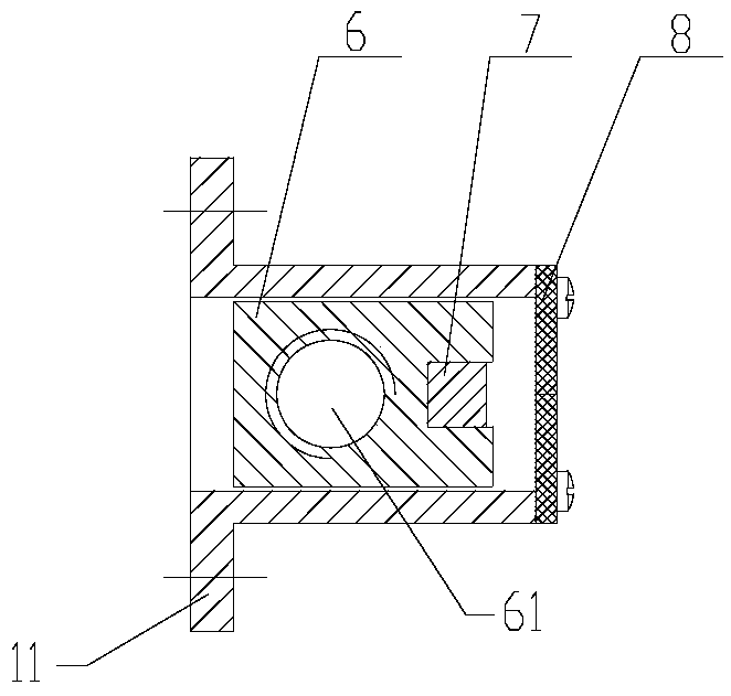
[0019] To achieve this objective, the present invention includes a sensor body 1, which is a cuboid structure housing with a window 11 on the upper end surface. This structure housing is easier to install. A lead screw transmission device is provided in the sensor body, the lead screw 2 of the lead screw transmission device extends out of the sensor body 1, and a driven gear 4 is provided on the lead screw extending out of the sensor body. , The driven gear is fixed on the lead screw by a nut 5. The driven gear 4 meshes with the driving gear on the electric water injection tool of the oil field. Therefore, the power of the present invention comes from the oil field electric water injection tool, and first realizes the mechanical connection with the oil field electric water injection tool.
[0020] A stroke sensor circuit board 8 is provided on the upper end surface of the sensor body 1, and the stroke sensor circuit board 8 is connected to a power source by wires and feeds back signals. In this embodiment, the stroke sensor circuit board 8 is fixed on the upper end surface of the sensor body 1 with screws 9 through the mounting screw holes, and three wires are led out from the stroke sensor circuit board 8, two of which are power cords and one for power supply For the positive pole, one is the ground wire; the other is the signal wire, which is connected to the control system of the electric water injection tool in the oil field.
[0021] In this embodiment, the lead screw transmission device includes a lead screw 2 and a lead screw nut 6; in order to be able to accurately sense stroke change information, the lead screw nut 6 is a rectangular parallelepiped structure with a central screw hole. The upper surface of the screw nut 6 is provided with a groove, a magnet 7 is arranged in the groove, the groove is a rectangular groove, and the magnet 7 is a rectangular parallelepiped with an arc-shaped upper surface. magnet.
[0022] An adhesive layer is arranged between the magnet 7 and the groove, so that the magnet can be more firmly fixed in the groove. The magnet 7 described in this embodiment can be a permanent magnet.
[0023] A circlip 3 for limiting the axial position of the lead screw is provided in the sensor body 1 near one end of the driven gear, so that the axial position of the lead screw can be effectively limited.
[0024] In order to facilitate the installation of the present invention in the electric water injection tool of the oil field, the lower end surface of the sensor body 1 is provided with an outwardly turned fixed edge 11 with a fixed screw hole 10. The present invention can be directly fixed on the electric water injection tool of the oil field by passing the screw through the fixing screw hole 10. Such as Figure 4 Shown in: the present invention is fixed on the main body 16 of the oil field electric water injection tool through the mounting screw hole 14 on the oil field electric water injection tool and the fixing hole 10 of the present invention. The driving gear 13 of the oil field electric water injection tool main body 16 is connected with the slave of the present invention. The driving gear 4 meshes. When the driving wheel 13 rotates, the driven gear 4 is driven to rotate together, and the driven gear drives the screw 2 to rotate, driving the screw nut 6 and the magnetic block 7 on it to move axially along the screw. At this time, the sensing element on the sensor circuit board 8 can perceive the change of the magnetic field, and the position of the screw nut 6 can be determined through the signal of the sensor feedback circuit to complete the accurate stroke control and valve position feedback of the water distribution valve in the oil field water injection tool.

PUM

no PUM

Description & Claims & Application Information

We can also present the details of the Description, Claims and Application information to help users get a comprehensive understanding of the technical details of the patent, such as background art, summary of invention, brief description of drawings, description of embodiments, and other original content. On the other hand, users can also determine the specific scope of protection of the technology through the list of claims; as well as understand the changes in the life cycle of the technology with the presentation of the patent timeline. Login to view more.

Similar technology patents

Classification and recommendation of technical efficacy words

  • Simple structure
  • Easy installation

Microlithographic projection exposure apparatus

InactiveUS20050068499A1Simple structureReliable and low-maintenance operationProjectorsPhotomechanical exposure apparatusCamera lensPhysics
Owner:CARL ZEISS SMT GMBH
Why Eureka
Try Eureka