Stalling equipment of transmission shaft

A transmission shaft and equipment technology, applied in the field of transmission shaft stop equipment, can solve the problem of reducing the output precision of the driver, and achieve the effect of eliminating kinetic energy

Inactive Publication Date: 2019-01-11
袁学锋
View PDF0 Cites 3 Cited by
  • Summary
  • Abstract
  • Description
  • Claims
  • Application Information

AI Technical Summary

Problems solved by technology

[0002] With the development of science and technology and the progress of society, the country has been promoting the development of high technology. In the field of power output, there has always been a relatively difficult technical problem, that is, the output shaft will rotate for a certain period of time due to the inertia of some driving machines after they stop. Angle, resulting in lower output accuracy of the driver, so there is an urgent need for a device to solve such problems

Method used


Image

  • Stalling equipment of transmission shaft
  • Stalling equipment of transmission shaft
  • Stalling equipment of transmission shaft

Examples


Embodiment Construction

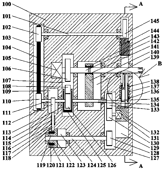
[0014] like Figure 1-Figure 3As shown, the stopping device of the transmission shaft of the present invention includes a fuselage 100, a first cavity 107 arranged in the fuselage 100 and a second cavity 127 arranged in the fuselage 100, the The first cavity 107, the third cavity 139 is arranged in the right end wall of the first cavity 107, the first sliding block 140 is slidably arranged in the third cavity 139, the first sliding A rotating sleeve 143 extending left and right is arranged in the block 140, and a spline hole 141 penetrating left and right is arranged in the rotation sleeve 143, and a first spline shaft 142 is spline-fitted in the spline hole 141. The end of the first spline shaft 142 extending to the left passes through the left end wall of the third cavity 139 and extends into the first cavity 107, and the end is fixedly arranged in the left end wall of the first cavity 107. The first motor 105 is power connected, the outer surface of the first spline shaft ...


PUM


Abstract

The invention discloses stalling equipment of a transmission shaft. The stalling equipment comprises a machine body, a first cavity formed in the machine body, and a second cavity formed in the machine body. A third cavity is formed in the end wall of the right side of the first cavity, a first sliding block is slidingly arranged in the third cavity, a rotary sleeve stretching left and right is rotationally arranged in the first sliding block, and a spline hole which is through left and right is formed in the rotary sleeve. The equipment is simple in structure and convenient to operate, the same power source is adopted for driving power-on of a driver and separation of an output shaft of the driver, meanwhile, a locking block is driven to be mechanically connected with the driver, thus, the inertia of the output shaft is eliminated through power of the driver, sudden stop of the output shaft of the equipment is achieved, the output precision of the equipment is improved, meanwhile, thedriver can be automatically powered on, powered off and locked after kinetic energy is achieved, all the procedures cooperate but do not affect one another, and the practical performance of the device is improved.

Description

technical field [0001] The invention relates to the field of power output, in particular to a stopping device of a transmission shaft. Background technique [0002] With the development of science and technology and the progress of society, the country has been promoting the development of high technology. In the field of power output, there has always been a relatively difficult technical problem, that is, the output shaft will rotate for a certain period of time due to the inertia of some driving machines after they stop. Angle, resulting in lower output accuracy of the driver, so there is an urgent need for a device to solve such problems. Contents of the invention [0003] The technical problem to be solved by the present invention is to provide a device for stopping the transmission shaft, which can solve the above-mentioned problems in the prior art. [0004] The present invention is achieved through the following technical solutions: the stoppage device of the tran...

Claims


Application Information

Patent Timeline
Patent Type & Authority Applications(China)
IPC IPC(8): F16D55/224F16D65/14F16D121/24
CPCF16D55/224F16D65/14F16D2121/24
Inventor 袁学锋
Owner 袁学锋
Why Eureka
Try Eureka