Hydraulic torque converter cavitation inhibition method based on slotting

A torque converter and through-groove technology, applied in the field of vehicle transmission system, can solve the problems of torque converter vibration, reduce the degree of cavitation, noise and reliability, and improve the vibration and reduce the degree of cavitation. , the effect of reducing the degree of cavitation

Inactive Publication Date: 2019-01-11
BEIJING INSTITUTE OF TECHNOLOGYGY
View PDF5 Cites 4 Cited by
  • Summary
  • Abstract
  • Description
  • Claims
  • Application Information

AI Technical Summary

Problems solved by technology

[0004] In view of this, the present invention provides a method for suppressing cavitation of a hydraulic torque converter based on slotting, which can effectively reduce the degree of cavitation and solve the problems of vibration, noise and reliability reduction of the hydraulic torque converter due to cavitation

Method used


Image

  • Hydraulic torque converter cavitation inhibition method based on slotting
  • Hydraulic torque converter cavitation inhibition method based on slotting
  • Hydraulic torque converter cavitation inhibition method based on slotting

Examples


Embodiment 1

[0022] This embodiment provides a method for suppressing cavitation of a torque converter based on slotting, which can improve the cavitation of the torque converter by reducing the degree of cavitation by slotting on the vane of the guide wheel of the torque converter Noise, vibration and improved torque converter performance.

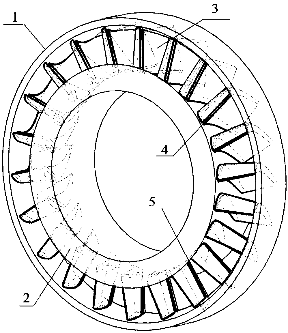
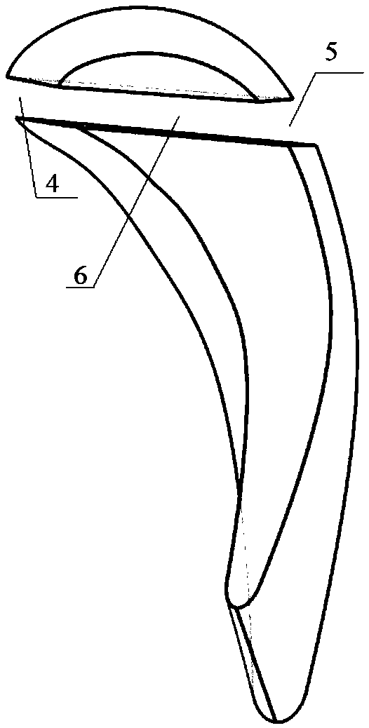
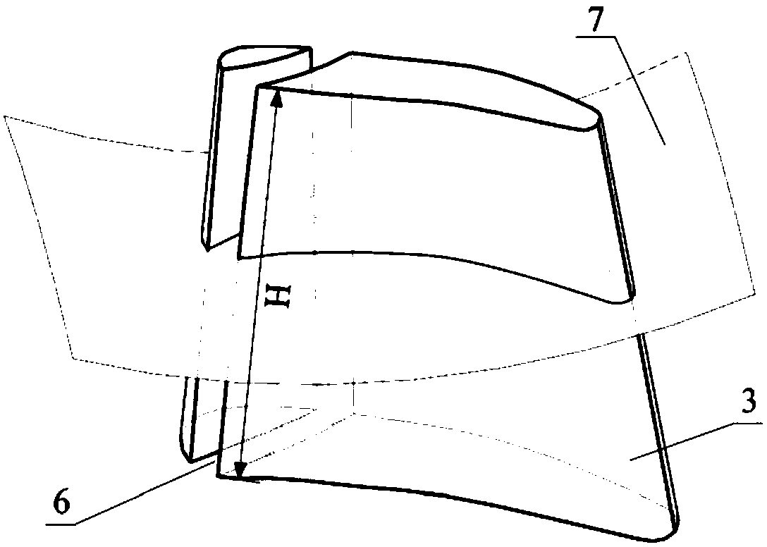
[0023] Such as figure 1 As shown, the guide wheel of the hydraulic torque converter includes a guide wheel outer ring 1, a guide wheel inner ring 2, and a plurality of guide wheel blades 3 evenly distributed between the guide wheel outer ring 1 and the guide wheel inner ring 2 along the circumferential direction . For suppressing cavitation, the head of each guide wheel blade 3 of the guide wheel is processed as figure 2 with image 3 The shown through groove 6 forms a grooved guide wheel, such as Figure 5 As shown, the through groove 6 is the same width groove, that is, the groove width W at each position along the depth direction of the throug...

Embodiment 2

[0027] Compared with the above-mentioned embodiment 1, the through groove 6 in this embodiment is a convergent groove, that is, the groove width gradually decreases along the depth direction of the through groove 6, so that the groove width of the through groove 6 at the groove outlet 5 is smaller than the groove at the groove inlet 4 end wide, such as Figure 7 shown. However, the converging groove is easy to form a strong jet at the outlet, and it is applied when the flow rate of the torque converter is small and the number of vanes of the guide wheel is small.

Embodiment 3

[0029] Compared with the above-mentioned embodiment 1, the through groove 6 in this embodiment is a divergent groove, that is, the groove width gradually increases along the depth direction of the through groove 6, so that the groove width of the through groove 6 at the groove outlet 5 is larger than the groove at the groove inlet 4 end wide, such as Figure 8 shown. The divergence groove can increase the drainage flow, and it is applied when the number of blades of the torque converter guide wheel is large.


PUM


Abstract

The invention discloses a hydraulic torque converter cavitation inhibition method based on slotting. The hydraulic torque converter cavitation inhibition method based on slotting can effectively reduce the degree of cavitation and solves the problems of vibration, noise and reliability reduction caused by cavitation of a hydraulic torque converter. The hydraulic torque converter cavitation inhibition method comprises the steps that a through groove is machined in the head portion of a guide wheel vane of the hydraulic torque converter, and liquid flow flowing through the guide wheel vane is subjected to flow dividing through the through groove; and when the hydraulic torque converter is operated, the liquid flow flows from an inlet to the middle portion of the vane through the through groove to form jet flow. The functions of flow guiding and re-jet flow blocking are achieved, the passive inhibition effect of the cavitation in the hydraulic torque converter is realized, and cavitationvibration, noise and negative effects thereof are reduced.

Description

technical field [0001] The invention relates to the field of vehicle transmission systems, in particular to a method for suppressing cavitation of a hydraulic torque converter based on slotting. Background technique [0002] The hydraulic torque converter is a hydraulic component composed of a pump wheel, a turbine, and a guide wheel. Installed between the engine and the transmission, with hydraulic oil as the working medium, it plays the role of torque transmission, torque conversion, speed change and clutch. The hydraulic torque converter has the ability of continuously variable torque and reducing vibration and shock, and is widely used in vehicle transmission systems such as cars, buses, and construction machinery. As the speed and power density of the vehicle transmission system further increase, the internal pressure of the torque converter becomes lower and lower. When it is lower than a certain threshold, cavitation occurs. The cavitation phenomenon will lead to th...

Claims


Application Information

Patent Timeline
Patent Type & Authority Applications(China)
IPC IPC(8): F16H41/26
CPCF16H41/26
Inventor 刘城闫清东项昌乐魏巍
Owner BEIJING INSTITUTE OF TECHNOLOGYGY
Why Eureka
Try Eureka