Secondary air system of boiler

A technology of secondary air and secondary air pipe, which is applied in the transportation of non-flammable liquid/gas, lighting and heating equipment, fluidized bed combustion equipment, etc., can solve the problem of poor penetration of secondary air and achieve Solve the effect of poor penetration

Active Publication Date: 2019-01-11
YANTAI LONGYUAN POWER TECH
View PDF8 Cites 2 Cited by
  • Summary
  • Abstract
  • Description
  • Claims
  • Application Information

AI Technical Summary

Problems solved by technology

[0005] The purpose of the present invention is to provide a boiler secondary air system to solve the problem that the secondary air penetration of the existing boiler secondary air system is not good when the load decreases

Method used


Image

  • Secondary air system of boiler
  • Secondary air system of boiler

Examples


Embodiment Construction

[0022] The technical solutions of the present invention will be further described below in conjunction with the accompanying drawings and through specific implementation methods.

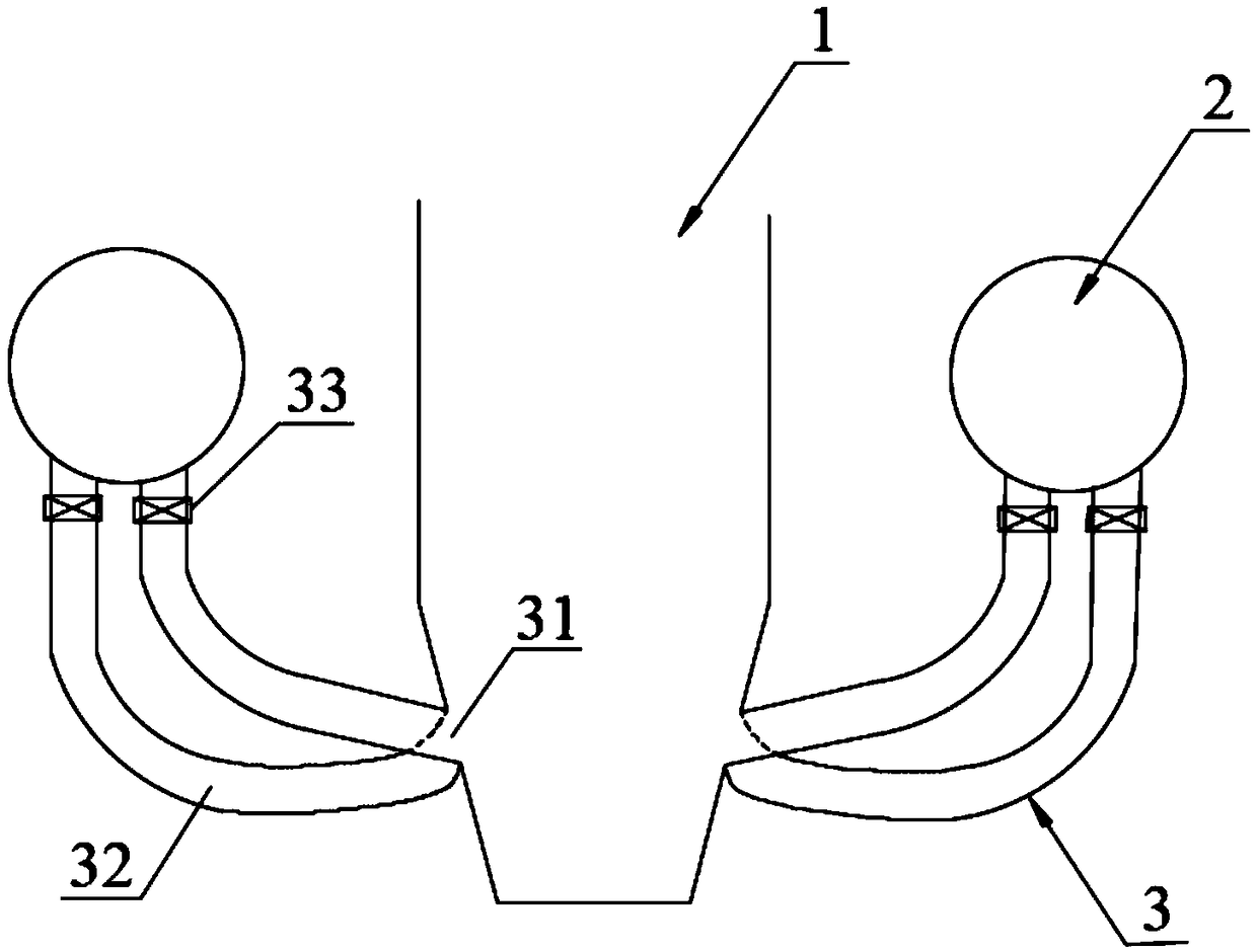
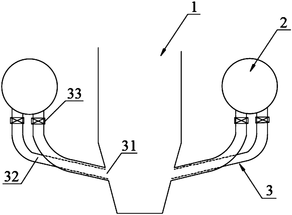
[0023] Such as figure 1 and figure 2 As shown, all of them are structural schematic diagrams of the boiler secondary air system provided by the present invention. The boiler secondary air system includes a furnace 1 and a secondary air box 2 connected to the furnace 1. The secondary air box 2 is connected to multiple sets of secondary air pipes 3, and each set of secondary air pipes 3 has a nozzle 31 corresponding to the furnace 1. Each group of secondary air pipes 3 includes at least two secondary air branch pipes 32; in each group of secondary air pipes 3, each secondary air branch pipe 32 is located at one end of the secondary air box 2 and is separated from each other, and is located at one end of the furnace 1 All communicate with the nozzles 31 corresponding to the group of secondary air du...


PUM


Abstract

The invention belongs to the technical field of boiler modification, and discloses a secondary air system of a boiler. The secondary air system of the boiler comprises a hearth and a secondary air bellow connected with the hearth, wherein the secondary air box is connected with a plurality of groups of secondary air pipes, and each group of secondary air pipes and the hearth are correspondence with one nozzle, and each group of secondary air pipes comprise at least two secondary air branch pipes; and in each group of secondary air pipes, each secondary air branch pipe is located at one end ofthe secondary air bellow in a separating mode, and the other end of each secondary air branch pipe located in one side of the hearth is connected with the corresponding nozzle of the secondary air pipes. According to the boiler, by arranging the mode that each secondary air branch pipe is arranged at one end of the secondary air bellow in the separating mode, and one end of each secondary air branch pipe located in one end of the hearth communicates with the corresponding nozzle of each secondary air pipe, so that when a load is reduced, one of secondary air branch pipes can be turned down orturned off, the flow speed of other secondary air branch pipes in the group of secondary air pipes is not influenced, so that the momentum of secondary air passing through the nozzle is maintained, and the problem that the secondary air permeability is poor due to the fact that the load is reduced is solved.

Description

technical field [0001] The invention relates to the technical field of boiler transformation, in particular to a boiler secondary air system. Background technique [0002] In a circulating fluidized bed boiler, the furnace is generally divided into three parts according to the concentration of the material: the dense phase zone, the transition zone and the dilute phase zone. Heat capacity. During the actual operation of the boiler, due to the relatively high concentration of solid particles in the dense-phase area, the bed layer exhibits a relatively high furnace positive pressure, which makes the penetration resistance of the secondary air flow very large, and it is difficult to send the air into the dense-phase area. Oxygen often shows a distribution trend of high around and low in the middle. For fluidized bed boilers, the primary air needs to ensure the normal fluidization of the boiler, and there is a minimum fluidization air volume limit. The secondary air mainly pla...

Claims


Application Information

Patent Timeline
Patent Type & Authority Applications(China)
IPC IPC(8): F23C10/18F23L9/00
CPCF23C10/18F23L9/00F23C2206/10
Inventor 王家兴王超王勇彭建升程昌业高全崔强杜雨琛
Owner YANTAI LONGYUAN POWER TECH
Why Eureka
Try Eureka