
Automatic shaft type detection method

An automatic detection and shaft type technology, which is applied in the direction of mechanical bearing testing, measuring devices, instruments, etc., can solve the problems that small motor shafts cannot be detected, cannot detect whether all shafts have reached the specified position, and detect unfavorable positions. Not easily affected by external environment, reliable detection method and long service life

Active Publication Date: 2019-01-11
CHANGZHOU DINGS ELECTRICAL & MECHANICAL
View PDF6 Cites 0 Cited by
  • Summary
  • Abstract
  • Description
  • Claims
  • Application Information

AI Technical Summary

Problems solved by technology

[0002] For some small motors such as small stepping motors, synchronous motors, etc., in the production and assembly process, there has always been the problem that the position of the small motor shaft cannot be detected before assembly
When the number of motor shafts that need to be assembled at the same time is large, the spatial position distribution is mixed, and the distance between the shafts is small, the photoelectric sensor detection device is usually used to directly detect the placement position of a single shaft, but this detection method The detected motor shaft interferes with other motor shafts to be detected in space, which is not conducive to the position detection
In addition, ordinary mechanical mechanisms are often used for position detection, but the mechanical mechanism is limited to a small space, and it is impossible to detect whether all the identification axes have reached the specified position

Method used


Image

  • Automatic shaft type detection method
  • Automatic shaft type detection method
  • Automatic shaft type detection method

Examples


Embodiment 1

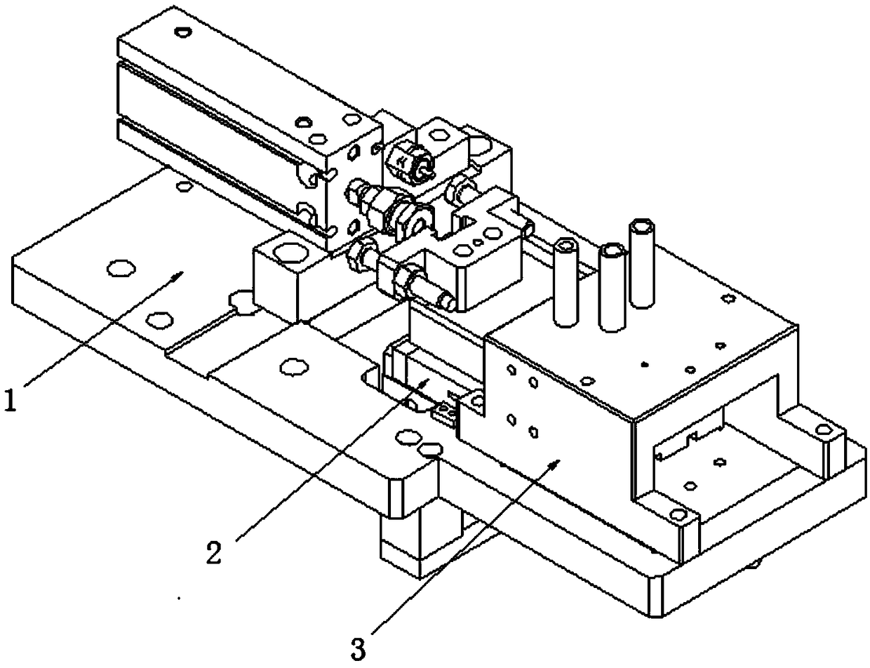
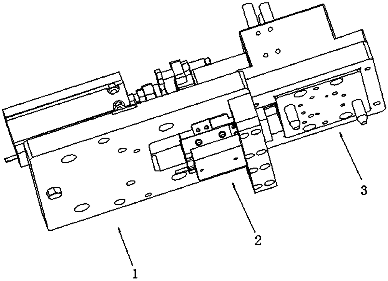
[0050] Such as Figure 1 to Figure 7 As shown, a shaft automatic detection mechanism includes a guide assembly 3 and a detection assembly 2 .

[0051] The guide assembly 3 includes a first guide plate 31 and a push plate 32, the first guide plate 31 is provided with a plurality of first guide holes 311, the push plate 32 is arranged on the first guide plate 31, and the first guide holes 311, and the position corresponding to the first guide hole 311 on the push plate 32 is provided with a detection through hole 321, and the detection through hole 321 is coaxial with the first guide hole 311 and corresponds one by one, so that the shaft type The component enters the corresponding detection through hole 321 through the first guide hole 311 . When the push plate 32 is in the initial state, the first guide hole 311 on the first guide plate 31 is coaxial with the detection through hole 321 on the push plate 32, and the shaft (such as a small motor shaft) passes through the first g...

Embodiment 2

[0057] In this embodiment 2, on the basis of the embodiment 1, the structure of the detection assembly 2 is further optimized, so that all shafts in the detection through hole can be accurately detected.

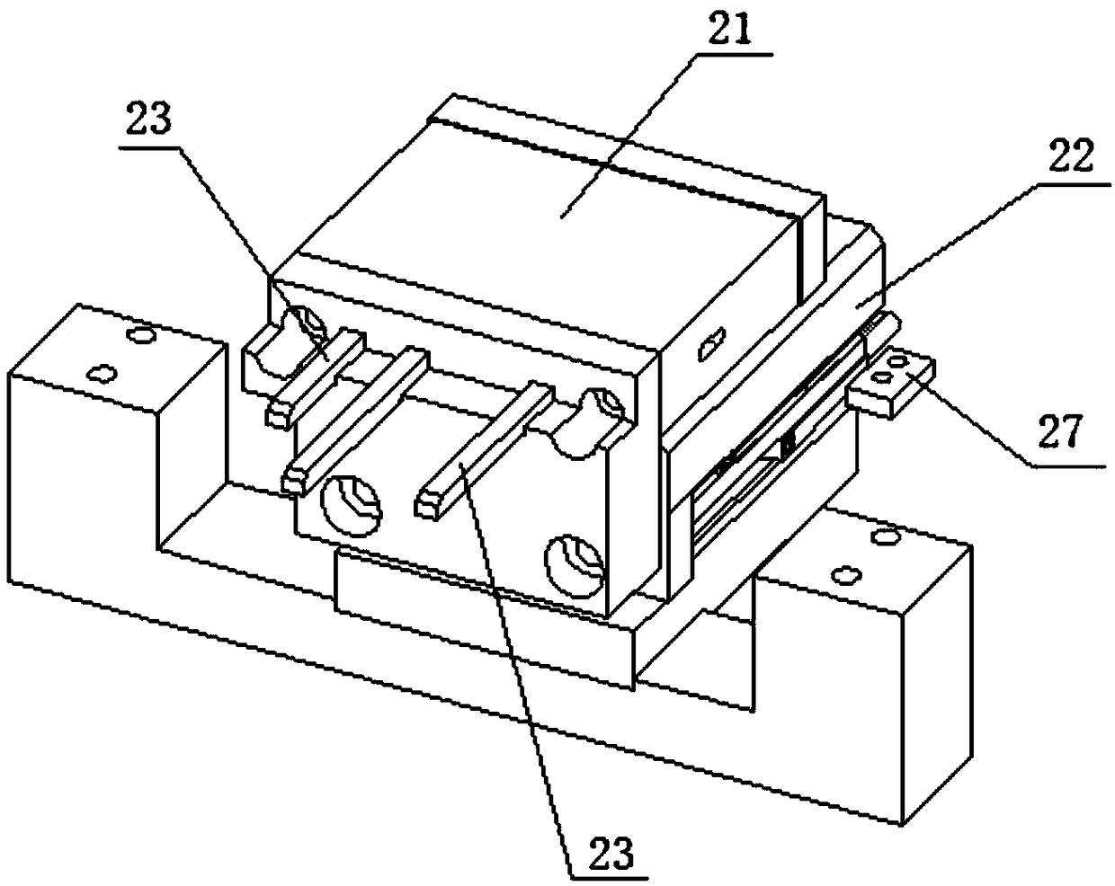
[0058] Such as Figure 3 to Figure 4 , Figure 8 to Figure 9 As shown, the detection assembly 2 also includes a guide pin mounting block 21 , a spring cover plate, and a sliding platform connecting plate 26 .

[0059] The guide pin installation block 21 is provided with a guide pin installation hole 211 , and the guide pin installation hole 211 is used for accommodating the detection needle 23 and providing space for the detection needle 23 to slide back and forth. The detection pin 23 is slidably inserted into the guide pin installation hole 211 . The guide pin mounting block 21 is assembled on the slide table 22 through the slide table connecting plate 26 . The slide table 22 can use a slide table cylinder as a power source for the detection needle 23 . The slide table...

Embodiment 3

[0067] On the basis of Embodiment 2, in order to automatically drive the shaft parts in the push plate 32 to carry out precise assembly, as Figure 1 to Figure 14 As shown, in the present embodiment 3, the shaft automatic detection mechanism also includes a push assembly 1, and the push assembly 1 includes a cylinder 11 and a cylinder push block 13, and the cylinder push block 13 is fixedly connected to the piston rod of the cylinder 11, and the cylinder push block 13 is also fixedly connected with the push plate 32 of the guide assembly, and the push plate 32 is slidably assembled on the first guide plate 31 so that the cylinder 11 pushes the push plate 32 to slide back and forth along the first guide plate 31 . The cylinder provides power for the sliding of the push plate 32 along the first guide plate 31. The piston rod of the cylinder 11 is equipped with a cylinder push block 13, which indirectly drives the push plate 32 to move through the connection between the cylinder p...


PUM


Abstract

The invention discloses an automatic shaft type detection method. The method comprises the following steps of: S1, assembling shaft parts into a guide assembly for positioning; and S2, detecting the shaft part assembled in the guide assembly by using a detection assembly. The detection assembly comprises a sliding table and detection needles. The detection needles are driven by the sliding table to move. Whether the shaft parts are in place or not is accurately detected by means of the detection needles touching the shaft parts in the guide assembly. According to the automatic shaft type detection method, the detection needles are driven by the sliding table to detect the shaft parts in the guide assembly; whether the shaft parts are in place or not, and whether missing shaft or shaft deformation exists or not are detected by the means of the detection needles touching the shaft parts; the mechanism is reliable in detection mode, and light and compact in structure; and whether a shaft,shaft deformation or the like exists in each detection through hole can be accurately detected in a narrow space.

Description

technical field [0001] The invention relates to an automatic shaft detection method, which belongs to the technical field of shaft detection. Background technique [0002] For some small motors such as small stepping motors, synchronous motors, etc., in the production and assembly process, there has always been a problem that the position of the small motor shaft cannot be detected before assembly. When the number of motor shafts that need to be assembled at the same time is large, the spatial position distribution is mixed, and the distance between the shafts is small, the photoelectric sensor detection device is usually used to directly detect the placement position of a single shaft, but this detection method The detected motor shaft interferes with other motor shafts to be detected in space, which is not conducive to the position detection. In addition, ordinary mechanical mechanisms are often used for position detection, but the mechanical mechanism is limited to a sma...

Claims


Application Information

Patent Timeline
Patent Type & Authority Applications(China)
IPC IPC(8): G01B11/16G01M13/04G01V8/10
CPCG01B11/16G01M13/04G01V8/10
Inventor 谈金锋黄豫晴戴强周志光杨炼
Owner CHANGZHOU DINGS ELECTRICAL & MECHANICAL
Learn More