A method for measuring the spectral reflectance of a full-scale object surface

A technology of spectral reflectance and object surface, which is applied in the field of photoelectric detection, can solve the problems that are not suitable for testing the spectral reflectance of the surface of high reflectivity objects, and test the error of samples with low reflectivity, so as to achieve convenient and fast operation and small error of test data Effect

Active Publication Date: 2021-06-18
SHENZHEN THREE BEAM COATING TECH CO LTD
View PDF8 Cites 0 Cited by
  • Summary
  • Abstract
  • Description
  • Claims
  • Application Information

AI Technical Summary

Problems solved by technology

But the applicant finds that when using the spectrophotometer to test the lower workpiece surface of spectral reflectance (such as flat glass workpiece, AR coating workpiece, etc.), a smaller test electrical signal intensity En is read during actual testing, because This En is so small that it exceeds the linear region where the E1n read when doing "normalization" calibration, resulting in a large error when it tests low-reflectance samples. This spectrophotometer is only suitable for testing workpieces with high spectral reflectance
[0005] Another array spectrophotometer commonly used in existing reflectance testing experiments is widely used to measure the spectral reflectance after the optical lens is coated with AR film, but it is not suitable for testing high reflectivity objects. The spectral reflectance of the surface, read a larger test electrical signal strength En during the actual test, because this En is too large to exceed the linear region where the Ekn read during the "reduction" calibration, causing it to test high reflectance There will be a large error when measuring the ratio of the sample, the spectrophotometer is only suitable for testing workpieces with low spectral reflectance

Method used


Image

  • A method for measuring the spectral reflectance of a full-scale object surface
  • A method for measuring the spectral reflectance of a full-scale object surface
  • A method for measuring the spectral reflectance of a full-scale object surface

Examples


specific Embodiment 1

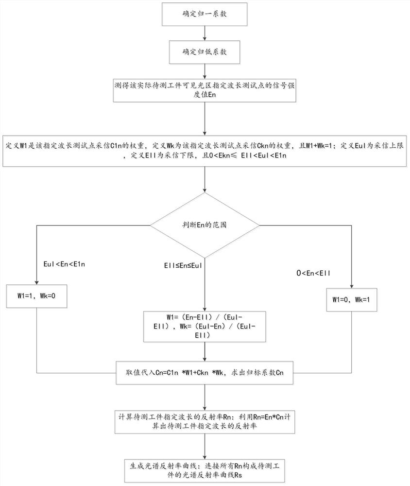
[0040] see figure 1 and figure 2 , the present invention provides a method for testing the spectral reflectance of a full-scale object surface, the method includes the following steps:

[0041] S1: Determine the normalization coefficient: place the 100% reflectance calibration reference sheet on the spectrometer carrier, measure the signal intensity value E1n of the specified wavelength test point in the visible light region of the reference sheet, and calculate the normalization coefficient according to E1n C1n;

[0042] S2: Determine the reduction coefficient: place the low-reflectivity calibration reference sheet on the spectrometer's carrier, measure the signal intensity value of the specified wavelength test point in the visible region of the reference sheet as Ekn, and calculate the reduction coefficient Ckn according to Ekn ;

[0043] S3: Measure the signal strength of the test point at the specified wavelength in the actual visible light region of the workpiece: p...

specific Embodiment 2

[0063] see figure 1 and image 3 , the present invention provides a method for testing the spectral reflectance of a full-scale object surface, the method includes the following steps:

[0064] S1: Determine the normalization coefficient: place the 100% reflectance calibration reference sheet on the spectrometer carrier, measure the signal intensity value E1n of the specified wavelength test point in the visible light region of the reference sheet, and calculate the normalization coefficient according to E1n C1n;

[0065] S2: Determine the reduction coefficient: place the low-reflectivity calibration reference sheet on the spectrometer's carrier, measure the signal intensity value of the specified wavelength test point in the visible region of the reference sheet as Ekn, and calculate the reduction coefficient Ckn according to Ekn ;

[0066] S3: Measure the signal strength of the test point at the specified wavelength in the actual visible light region of the workpiece: pl...

specific Embodiment 3

[0086] see figure 1 and Figure 4 , the present invention provides a method for testing the spectral reflectance of a full-scale object surface, the method includes the following steps:

[0087] S1: Determine the normalization coefficient: place the 100% reflectance calibration reference sheet on the spectrometer carrier, measure the signal intensity value E1n of the specified wavelength test point in the visible light region of the reference sheet, and calculate the normalization coefficient according to E1n C1n;

[0088] S2: Determine the reduction coefficient: place the low-reflectivity calibration reference sheet on the spectrometer's carrier, measure the signal intensity value of the specified wavelength test point in the visible region of the reference sheet as Ekn, and calculate the reduction coefficient Ckn according to Ekn ;

[0089] S3: Measure the signal strength of the test point at the specified wavelength in the actual visible light region of the workpiece: p...


PUM


Abstract

The invention discloses a method for testing the surface reflectance of a full-scale object. The method first uses a 100% reflectance calibration reference sheet to determine the signal strength value E1n and normalization coefficient C1n of the specified wavelength, and secondly uses a low reflectance calibration reference sheet to determine The signal strength value of the specified wavelength is Ekn and the reduction coefficient Ckn. After measuring the signal strength En of the specified wavelength test point in the actual visible light region of the workpiece, determine the confidence weights assigned to C1n and Ckn according to the range that En falls into, and calculate the normalized value. The scalar coefficient Cn finally determines the specified wavelength position Rn. Testers use the reference calibration sheet to determine the normalization coefficient and reduction coefficient, and further determine the normalization coefficient Cn. The test data error in the whole process is small, applicable to the full range, and the operation is convenient and fast.

Description

technical field [0001] The invention belongs to the technical field of photoelectric detection, in particular to a method for testing the spectral reflectance of a full-scale object surface. Background technique [0002] In recent years, vacuum coating technology has developed rapidly and has been widely used, and its economic volume is huge. Vacuum coating products are usually mirror surfaces. The surface spectral reflectance curves of the coated products produced by different coating materials have different shapes, and the shape of the spectral reflectance curve of the coated surface directly represents the difference in the apparent color of the coated surface. The values ​​of spectral reflectance on the surface of different coating products range from a few percent to tens of percent, and the value span is quite large. In actual operation, a spectrophotometer is often used to detect the finished quality of coated products. [0003] The spectrophotometer mainly uses t...

Claims


Application Information

Patent Timeline
Patent Type & Authority Patents(China)
IPC IPC(8): G01N21/27
CPCG01N21/27
Inventor 战永刚战捷程明望
Owner SHENZHEN THREE BEAM COATING TECH CO LTD
Why Eureka
Try Eureka