An indoor test platform for hydraulic oscillator

A technology of hydraulic oscillator and test platform, which is applied in the testing of machine/structural components, testing of mechanical components, instruments, etc., can solve the problems of experimental data error, decrease of test data accuracy, and poor flexibility of test experimental data operation.

Active Publication Date: 2017-12-05
CHINA NAT PETROLEUM CORP CHUANQING DRILLING ENG CO LTD
View PDF6 Cites 0 Cited by
  • Summary
  • Abstract
  • Description
  • Claims
  • Application Information

AI Technical Summary

Problems solved by technology

[0006] The experimental device for testing the performance of the hydraulic oscillator disclosed in this patent document, during the test experiment, inserts and installs the oscillating joint of the hydraulic oscillator into the assembly holes of the installation disc A and the installation disc B, and the hydraulic oscillator The power nipple is inserted and installed in the assembly hole of the installation disc C to realize the clamping of the hydraulic oscillator. The clamping fixed position is relatively fixed, it is difficult to realize the free adjustment of the height, and the flexibility of the test data operation is poor; through Screw in the compression nut to compress the spring to obtain different pressures to simulate the application of drilling pressure, but it is difficult to provide a stable axial thrust for the hydraulic oscillator, resulting in errors in the experimental data obtained from the test and a decrease in the accuracy of the test data

Method used


Image

  • An indoor test platform for hydraulic oscillator
  • An indoor test platform for hydraulic oscillator
  • An indoor test platform for hydraulic oscillator

Examples


Embodiment 1

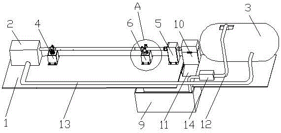
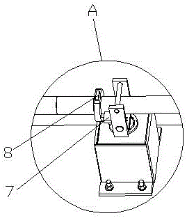
[0054] see figure 1 and figure 2 , a hydraulic oscillator indoor test platform, comprising a mounting base plate 1, a pump unit 2 fixed at one end of the mounting base plate 1 and a water storage tank 3 fixed at the other end of the mounting base plate 1, the mounting base plate 1 is connected to There is a clamping device 4 for clamping the hydraulic oscillator and a pressurizing device 5 for pressurizing the hydraulic oscillator, the clamping device 4 is close to the pump group 2, the pressurizing device 5 is close to the water storage tank 3, the A sliding support device 6 for sliding the hydraulic oscillator is also connected to the installation seat plate 1, the sliding support device 6 is located between the clamping device 4 and the pressurizing device 5, and the impact force sensor is connected to the sliding support device 6 7. A frequency sensor 8 is connected to the outer circular boss of the hydraulic oscillator, a water collection tank 9 is connected below the i...

Embodiment 2

[0057] see Figure 1-Figure 3 , a hydraulic oscillator indoor test platform, comprising a mounting base plate 1, a pump unit 2 fixed at one end of the mounting base plate 1 and a water storage tank 3 fixed at the other end of the mounting base plate 1, the mounting base plate 1 is connected to There is a clamping device 4 for clamping the hydraulic oscillator and a pressurizing device 5 for pressurizing the hydraulic oscillator, the clamping device 4 is close to the pump group 2, the pressurizing device 5 is close to the water storage tank 3, the A sliding support device 6 for sliding the hydraulic oscillator is also connected to the installation seat plate 1, the sliding support device 6 is located between the clamping device 4 and the pressurizing device 5, and the impact force sensor is connected to the sliding support device 6 7. A frequency sensor 8 is connected to the outer circular boss of the hydraulic oscillator, a water collection tank 9 is connected below the instal...

Embodiment 3

[0061] see Figure 1-Figure 3 , a hydraulic oscillator indoor test platform, comprising a mounting base plate 1, a pump unit 2 fixed at one end of the mounting base plate 1 and a water storage tank 3 fixed at the other end of the mounting base plate 1, the mounting base plate 1 is connected to There is a clamping device 4 for clamping the hydraulic oscillator and a pressurizing device 5 for pressurizing the hydraulic oscillator, the clamping device 4 is close to the pump group 2, the pressurizing device 5 is close to the water storage tank 3, the A sliding support device 6 for sliding the hydraulic oscillator is also connected to the installation seat plate 1, the sliding support device 6 is located between the clamping device 4 and the pressurizing device 5, and the impact force sensor is connected to the sliding support device 6 7. A frequency sensor 8 is connected to the outer circular boss of the hydraulic oscillator, a water collection tank 9 is connected below the instal...


PUM


Abstract

The invention discloses a hydraulic oscillator indoor testing platform, which belongs to the technical field of drilling tools. The hydraulic oscillator indoor testing platform comprises a mounting seat plate, a pump set and a water storage tank, and is characterized in that the mounting seat plate is connected with a clamping device and a pressurization device; the mounting seat plate is also connected with a sliding supporting device; the sliding supporting device is connected with a hitting force sensor; the outer round boss of the hydraulic oscillator is connected with a frequency sensor; a water collection groove is connected below the mounting seat plate and a water collection tank is connected below the mounting seat plate; the water collection tank and the water collection groove are connected via a diversion groove; a water inlet pipe and a water outlet pipe are arranged on the water storage tank; a water pump is connected onto the water inlet pipe; the water collection groove is connected with the water storage tank via the water inlet pipe; and the pump set is connected with the water storage tank via the water outlet pipe. The testing platform can clamp, fix and apply axial thrust to the hydraulic oscillator, the downhole working environment can be simulated truly, testing data errors can be reduced effectively, and the experimental data precision is higher after testing.

Description

technical field [0001] The invention relates to the technical field of drilling tools, in particular to an indoor testing platform of a hydraulic oscillator. Background technique [0002] The hydraulic oscillator can effectively solve the problems of under pressure and slow ROP in the drilling process. The hydraulic oscillator reduces drilling friction through high-frequency axial vibration, effectively applies drilling pressure, and can effectively increase the ROP. [0003] The main indicators of the hydraulic oscillator are axial vibration force, vibration frequency and vibration displacement. In order to ensure that the newly developed hydraulic oscillator meets the design indicators in the application, it is necessary to test the newly developed hydraulic oscillator indoors to check whether its functionality, reliability and main indicators meet the design requirements. [0004] In order to truly simulate the working environment of the hydraulic oscillator in the well ...

Claims


Application Information

Patent Timeline
Patent Type & Authority Patents(China)
IPC IPC(8): G01M13/00
Inventor 何超胡畔李伟成刘彬姚建林
Owner CHINA NAT PETROLEUM CORP CHUANQING DRILLING ENG CO LTD
Why Eureka
Try Eureka