A high-precision image stabilization mirror bonding device and method

A technology of bonding device and mirror, applied in installation, instrumentation, optics, etc., can solve the problems of poor precision, poor consistency, weak strength, etc., to improve the yield, reduce adverse effects, and facilitate mass production and processing. Effect

Active Publication Date: 2021-02-23
BEIJING INST OF REMOTE SENSING EQUIP
View PDF17 Cites 0 Cited by
  • Summary
  • Abstract
  • Description
  • Claims
  • Application Information

AI Technical Summary

Problems solved by technology

[0003] The invention provides a high-precision image stabilization mirror bonding device and method, which solves the problems of poor bonding precision, low efficiency, weak strength and poor consistency of the existing devices and methods

Method used


Image

  • A high-precision image stabilization mirror bonding device and method
  • A high-precision image stabilization mirror bonding device and method
  • A high-precision image stabilization mirror bonding device and method

Examples


Embodiment 1

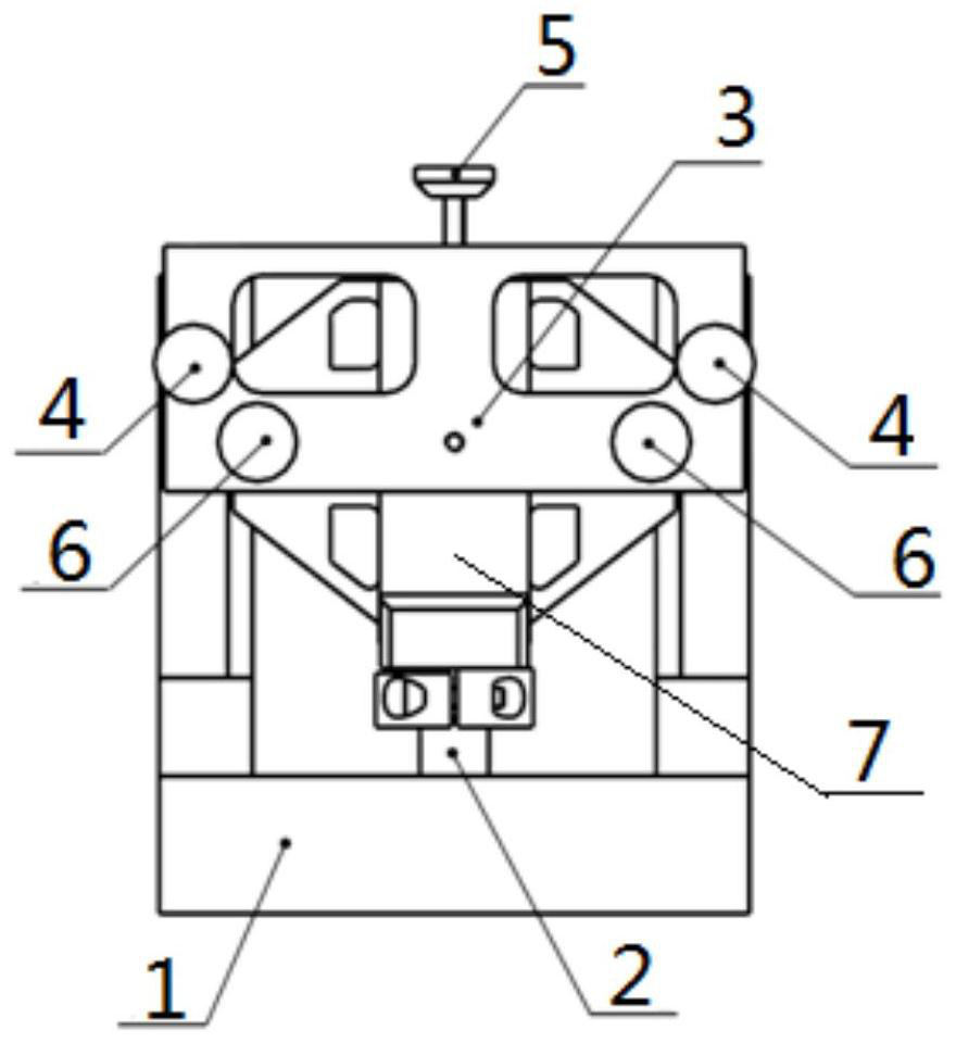
[0036] In combination with the above technical solution, in this embodiment, further, a second adjustment screw and a third adjustment screw are arranged on the adjustment pressure plate; the second adjustment screw is used to adjust the reflector on the mirror holder and the The contact accuracy of the base, the third adjusting screw is used to adjust the contact accuracy between the pressure plate and the mirror holder.

[0037] When using the high-precision image stabilization mirror bonding device described in this embodiment to bond the mirror, the two bonding surfaces of the mirror are coated with adhesive, and the mirror is inserted into the recess of the mirror holder. In the mouth; after the adjusting pressure plate and the base are fixedly connected by the first adjusting screw, the second adjusting screw is rotated so that the bottom end of the reflector is in close contact with the bottom surface of the notch of the mirror holder, and the rotating The third adjusti...

Embodiment 2

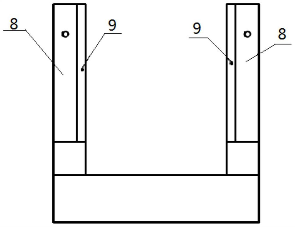
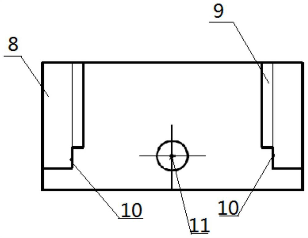
[0039] In combination with the above-mentioned technical solution, in this embodiment, further, the two ends of the base are respectively provided with adjusting platen fixing devices 8, and the two ends of the adjusting platen are respectively fixed with the adjusting platen fixing device 8 by first adjusting screws. connect. Further, positioning devices 9 are fixedly arranged on the inside of the adjusting platen fixing device 8, and the adjusting platen fixing device 8 protrudes from the positioning device 9, so that the adjusting platen fixing device 9 and the positioning device 8 An L-shaped limiting surface is formed between them. Further, the two ends of the base are respectively provided with limiting devices 10, and each of the limiting devices 10 is perpendicular to and intersects with the positioning device 9 and the fixing device 8 of the adjusting platen located at the same end of the base, that is, the limiting The device 10 cooperates with the L-shaped limiting...

Embodiment 3

[0042]In combination with the above technical solution, in this embodiment, a positioning lens 12 is also included, and the positioning lens includes a first positioning surface 13, a second positioning surface 14 and a third positioning surface 15, and the first positioning surface is located on the second positioning surface. Between the positioning surface and the third positioning surface, the two ends of the first positioning surface are respectively in close contact with the positioning devices at both ends of the base, and the second positioning surface and the third positioning surface are respectively in contact with the concave of the mirror holder. The upper and lower surfaces of the mouth are in close contact.

[0043] Further, the distance h1 between the second positioning surface and the third positioning surface on the positioning lens is 4.2mm, the tolerance is -0.02mm to -0.04mm, the distance between the first positioning surface and the second positioning surf...


PUM


Abstract

The invention discloses a high-precision image stabilization mirror bonding device and method, and relates to the field of high-precision assembly of optical structures. It includes a base, a mirror holder, a cylindrical pin, an adjustment pressure plate, and a first adjustment screw; wherein: one end of the cylindrical pin is fixedly arranged in a positioning hole at the bottom of the base, and the other end is fixedly connected to the mirror holder; the adjustment pressure plate passes through The first adjusting screw is connected to the upper part of the base, and the adjusting pressure plate is used to control and adjust the position accuracy of the reflector on the mirror holder. The reflector and the mirror holder can be precisely bonded according to the size requirements, thereby improving the coincidence accuracy of the mirror surface and the axis of the mirror holder mounting hole, reducing the adverse effects of manual operation errors, improving the yield, high adhesion strength, and Easy to mass produce and process.

Description

technical field [0001] The invention relates to the field of high-precision assembly of optical structures, in particular to a high-precision image stabilization mirror bonding device and method. Background technique [0002] The high-precision image stabilization mirror is used to stabilize the imaging optical path in the optical imaging process. In order to stabilize the imaging, it is necessary to ensure that after the mirror rotates, the rotation axis coincides with the mirror surface, and the rotation axis of the mirror and the incident light axis of the optical path Intersecting and perpendicular, so the requirements for coincidence between the reflective surface of the mirror and the axis of the mounting hole of the mirror holder are very high. At present, the bonding technology is used to connect the mirror and the mirror holder. The existing bonding technology is that the operator directly adjusts the bonding gap by visual inspection. After the bonding is cured, the...

Claims


Application Information

Patent Timeline
Patent Type & Authority Patents(China)
IPC IPC(8): G02B7/182
CPCG02B7/182
Inventor 赵楠赵立霞
Owner BEIJING INST OF REMOTE SENSING EQUIP
Why Eureka
Try Eureka