Near-eye display device based on diffractive optical elements

A near-eye display, diffracted light technology, applied in optical components, optics, instruments, etc., can solve problems affecting user experience, wearing discomfort, and distance from human eyes, and achieve the effect of improving user experience and wearing comfort.

Inactive Publication Date: 2019-01-11
SHANGHAI JIAO TONG UNIV
View PDF6 Cites 12 Cited by
  • Summary
  • Abstract
  • Description
  • Claims
  • Application Information

AI Technical Summary

Problems solved by technology

This kind of design will not only keep the human eye away from the exit pupil, resulting in loss of field of view (FOV), but also cause discomfort when wearing it, thus affecting the user experience

Method used


Image

  • Near-eye display device based on diffractive optical elements
  • Near-eye display device based on diffractive optical elements
  • Near-eye display device based on diffractive optical elements

Examples


Embodiment 1

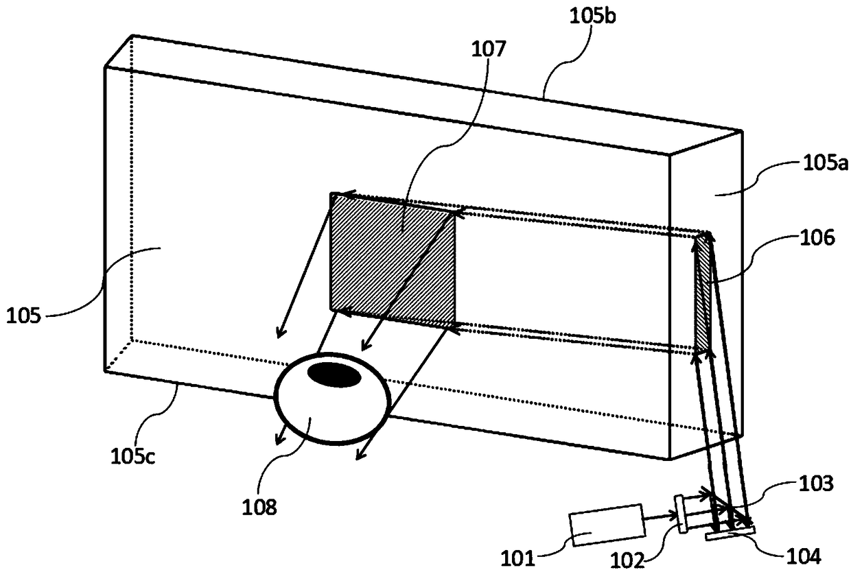
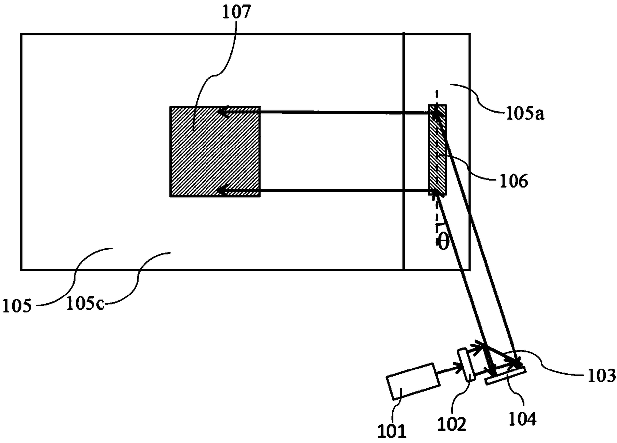
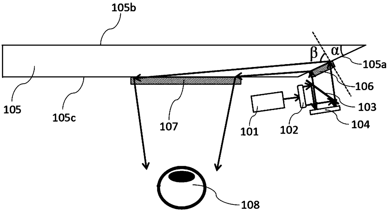
[0032] Such as figure 1 As shown, an optical display device based on a diffractive optical element involved in this embodiment includes: a laser 101, a beam shaper 102, a beam splitter 103, a reflective microdisplay 104, and a lens 105 with six surfaces. A first diffractive optical element 106 is attached to one surface 105a, and a second diffractive optical element 107 is attached to the third surface 105c.

[0033] In this embodiment, the laser 101 is an adjustable wavelength laser; the beam shaper 102 is a diffractive optical element or a holographic optical element; the beam splitter 103 is a non-polarizing beam splitter or a polarizing beam splitter; a reflective microdisplay The screen 104 is a silicon-based liquid crystal display or a digital micromirror display. Preferably, the silicon-based liquid crystal display is an amplitude-type spatial light modulator or a phase-type spatial light modulator; the material of the lens 105 is glass, resin, doped light The glass of...

Embodiment 2

[0038] Such as Figure 4As shown, an optical display device based on a diffractive optical element involved in this embodiment includes: a laser 201, a beam shaper 202, a beam splitter 203, a reflective microdisplay 204, and a lens 205 with six surfaces. A first diffractive optical element 206 is prepared on one surface 205a, a second diffractive optical element 207 is prepared on the third surface 205c, and the diopter of the third surface 205c depends on the user's vision;

[0039] In this embodiment, the laser 201 is an adjustable wavelength laser; the beam shaper 202 is a diffractive optical element or a holographic optical element; the beam splitter 203 is a non-polarizing beam splitter or a polarizing beam splitter; a reflective microdisplay The screen 204 is a silicon-based liquid crystal display or a digital micromirror display. Preferably, the silicon-based liquid crystal display is an amplitude-type spatial light modulator or a phase-type spatial light modulator; the...


PUM


Abstract

The invention discloses a near-eye display device based on diffractive optical elements. The device comprises a laser used for emitting collimated coherent light, a light beam shaper used for changingthe shape and the light intensity distribution of light spots, a beam splitter, a reflective micro display screen and a lens with at least six surfaces; the first diffractive optical element capableof deflecting light rays is manufactured or attached to the first surface of the lens; and the second diffractive optical element capable of allowing the light rays to be converged is manufactured orattached to the second surface or the third surface of the lens. According to the device, the exit pupil expansion can be realized by only two diffractive optical elements, and the second diffractiveoptical element can replace a projection lens, so that an imaging light path is greatly simplified on the whole. In addition, the device integrates an eyesight correcting function, so that a user doesnot need to additionally wear eyesight correcting lenses.

Description

technical field [0001] The present invention relates to a technology in the field of optical display equipment, in particular to a near-eye display device based on diffractive optical elements. Background technique [0002] Near-Eye Display (Near-Eye Display), also known as Head-Mounted Display (Head-Mounted Display), is one of the key technologies of augmented reality and a common visualization carrier for the virtual world and the real world. Since near-eye displays are wearable devices, higher requirements are placed on ergonomics. First, integrated vision correction is required. In recent years, the incidence of vision diseases such as myopia and hyperopia has continued to increase. For users suffering from the above vision diseases, when using near-eye display devices, such as smart glasses, augmented reality (AR) or virtual reality (VR) helmets, etc., it is necessary to wear an additional pair of glasses for vision correction. This type of design will not only keep ...

Claims


Application Information

Patent Timeline
Patent Type & Authority Applications(China)
IPC IPC(8): G02B27/00G02B27/01G02B27/09G02B27/42
CPCG02B27/0081G02B27/0101G02B27/0944G02B27/42G02B2027/0114
Inventor 陈超平张文博米岚田朱铭陆逸凡
Owner SHANGHAI JIAO TONG UNIV
Why Eureka
Try Eureka