Electromagnetic shielding structure of a photomultiplier tube
A technology of electromagnetic shielding structure and photomultiplier tube, which is applied in electron multiplier tube, discharge tube, tube/lamp screen manufacturing, etc., to achieve the effect of simple packaging process, reliable shielding effect, and reduced thickness of packaging shielding layer
- Summary
- Abstract
- Description
- Claims
- Application Information
AI Technical Summary
Problems solved by technology
Method used
Image
Examples
Embodiment 1
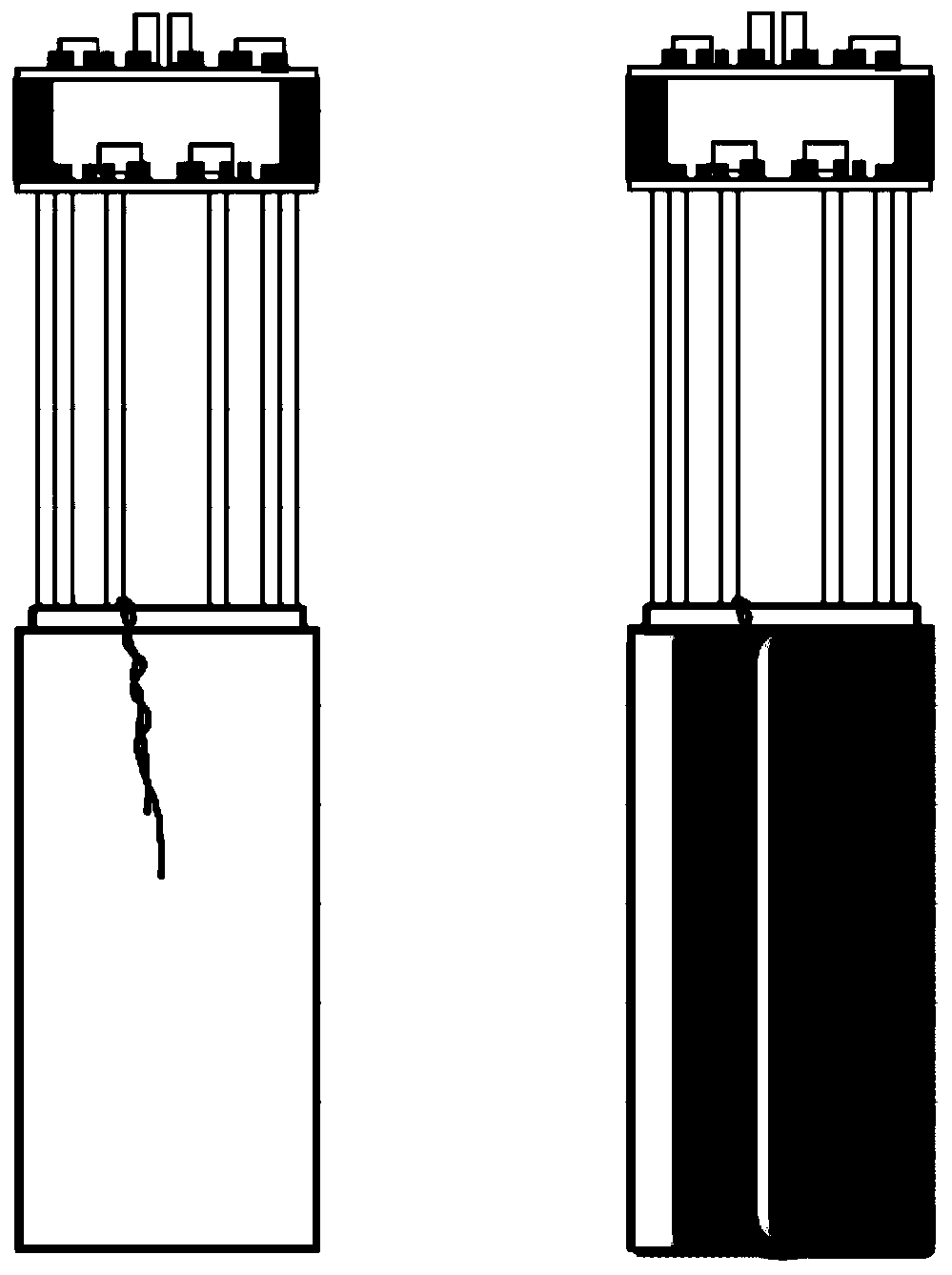
[0063] This embodiment provides an electromagnetic shielding structure of a photomultiplier tube, such as figure 1 As shown, the electromagnetic shielding structure of the photomultiplier tube includes:
[0064] The periphery of the tube body of the photomultiplier tube is sequentially provided with a shielding layer and an insulating layer; the shielding layer is a single-layer structure made of permalloy material.
[0065] The shielding layer is in contact with the pipe wall of the pipe body to shield the pipe body from electric and magnetic fields, and the insulating layer wraps the shielding layer to encapsulate and isolate the shielding layer from the outside world. The electrical isolation ensures the shielding effect of the shielding layer.
[0066] The shielding layer is connected to the corresponding pins of the photomultiplier tube, for example, for a photomultiplier tube that uses a positive high voltage, the above shielding layer is connected to the ground pin of ...
Embodiment 2
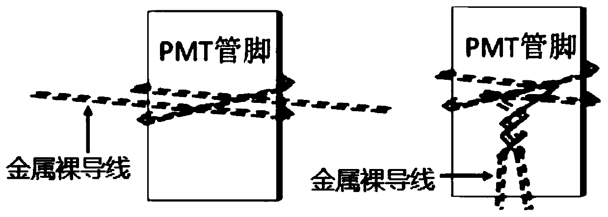
[0073] to combine Figure 2A and Figure 2B As shown, the present embodiment provides a method for setting the potential of the shielding layer of a photomultiplier tube, which may include the following steps:
[0074] S1. Select a bare metal wire for fixing the potential of the shielding layer.
[0075] Generally, wires with a thinner diameter have less influence on the thickness of the package. In this embodiment, thin bare metal wires with a diameter of less than 50 microns are preferred.
[0076] S2, tie the middle area of the bare metal wire to the ground pin (positive high voltage) / high voltage pin (negative high voltage) of the photomultiplier tube; stick the two ends of the bare metal wire to the body of the photomultiplier tube on the pipe wall.
[0077] see Figure 2A In the binding method shown, wrap the middle area of the bare metal wire around the ground pin (positive high voltage) / high voltage pin (negative high voltage) three times, and one of the three ...
Embodiment 3
[0093] In this embodiment, a wire setting method for fixing the potential of the shielding layer of the photomultiplier tube is provided, including:
[0094] M1. Select the bare metal wire used to fix the potential of the shielding layer;
[0095] M2, tie the middle area of the bare metal wire to the ground pin (positive high voltage) / high voltage pin (negative high voltage) of the photomultiplier tube; stick the two ends of the bare metal wire to the body of the photomultiplier tube On the pipe wall, so that the metal bare wire pasted on the pipe wall is connected to the shielding layer;
[0096] Wherein, the middle area of the bare metal wire goes around the pin several times, and the two taps are compressed by the wire when the wire is tightened;
[0097] Cross-twist the two ends of the bare metal wire into a rope and extend towards the pipe wall, and fix the rope-shaped wire on the pipe wall with double-sided adhesive;
[0098] M3. Use conductive silver paint to fix ...
PUM
 Abstract
Description
Claims
Application Information
 - R&D
- Intellectual Property
- Life Sciences
- Materials
- Tech Scout
- Unparalleled Data Quality
- Higher Quality Content
- 60% Fewer Hallucinations
Browse by: Latest US Patents, China's latest patents, Technical Efficacy Thesaurus, Application Domain, Technology Topic, Popular Technical Reports.
© 2025 PatSnap. All rights reserved.Legal|Privacy policy|Modern Slavery Act Transparency Statement|Sitemap|About US| Contact US: help@patsnap.com


