
Liquid injection method for a carbon fiber storage battery

A storage battery and carbon fiber technology, which is applied to battery components, circuits, electrical components, etc., can solve the problems of high density and difficulty in fully absorbing electrolyte, and achieve the effect of improving work efficiency

Active Publication Date: 2019-01-11
GUANGZHOU ZHUOYUE POWER NEW ENERGY CO LTD
View PDF9 Cites 0 Cited by
  • Summary
  • Abstract
  • Description
  • Claims
  • Application Information

AI Technical Summary

Problems solved by technology

[0003] Usually, there is no flowing electrolyte in the carbon fiber battery, and the filled electrolyte is absorbed on the AGM diaphragm in the carbon fiber battery, but as the capacity of the battery increases, the chemical substances in the battery become more and more dense. As the size increases, it becomes more and more difficult to fully absorb the electrolyte by relying solely on the AGM separator itself.

Method used


Image

  • Liquid injection method for a carbon fiber storage battery
  • Liquid injection method for a carbon fiber storage battery
  • Liquid injection method for a carbon fiber storage battery

Examples


Embodiment

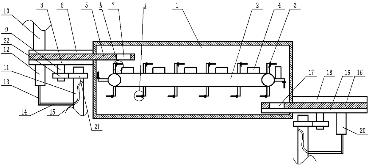
[0029] The continuous carbon fiber battery liquid injection equipment used in the liquid injection method of carbon fiber battery, such as figure 1 As shown, it includes a frame on which a vacuum tank 1 is fixed, and a transmission mechanism for transmitting batteries 4 is arranged in the vacuum tank 1. The transmission mechanism includes a conveyor belt 2, and a plurality of partitions 3 are evenly distributed on the conveyor belt 2 along the transmission direction. Placement cavities are formed between adjacent partitions 3 .

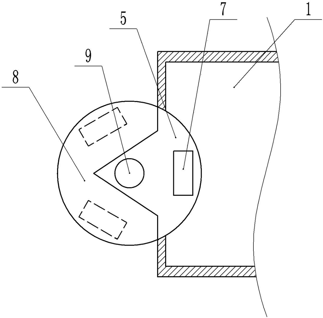
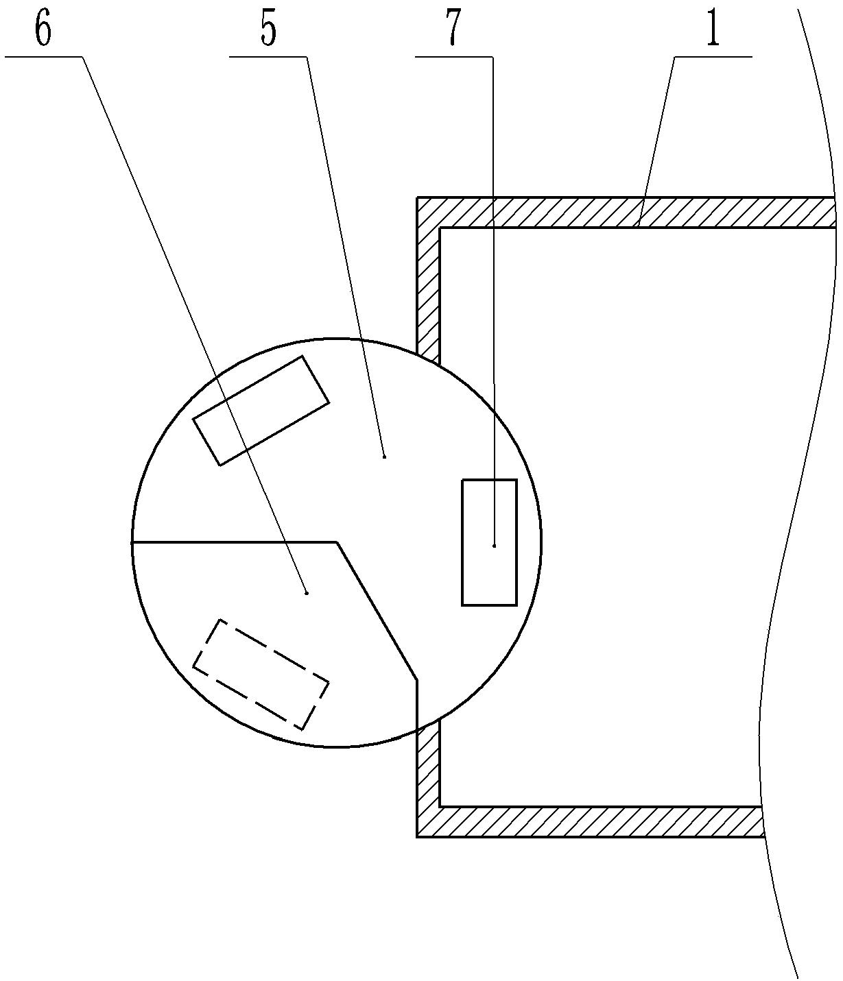
[0030] combine figure 2 , image 3 As shown, a feeding mechanism is arranged above the left end of the transmission mechanism on the frame. The feeding mechanism includes a first turntable 5 that is rotatably connected to the frame. area, the feeding area includes a first through hole 7 arranged on the first turntable 5 , and the size of the first through hole 7 is equal to the size of the battery 4 . The right end of the first turntable 5 runs th...


PUM


Abstract

The invention relates to a liquid injection method for a carbon fiber storage battery, comprising the following steps: step 1, placing the carbon fiber storage battery into a vacuum tank through a feeding mechanism, and arranging a liquid storage tank communicated with the vacuum tank beside the vacuum tank; 2, vacuumizing that vacuum tank, and aligning the liquid inject device with the liquid inlet of the carbon fiber storage battery; step 3, opening the liquid injection device and injecting the electrolyte solution in the liquid storage tank into the carbon fiber storage battery to completethe liquid injection operation, firstly transporting the carbon fiber storage battery to the end of the vacuum tank through a conveying mechanism, and then taking out the liquid injected carbon fiberstorage battery from the vacuum tank through a discharge mechanism to complete the processing. The present invention is intended to provide a liquid injection method for a carbon fiber storage batterycapable of improving the liquid injection efficiency of an electrolyte of the carbon fiber storage battery.

Description

technical field [0001] The invention relates to the technical field of carbon fiber storage battery processing, in particular to a liquid injection method for carbon fiber storage battery. Background technique [0002] There are many processes for manufacturing carbon fiber batteries, one of which is to charge the carbon fiber batteries with electrolyte. The addition of electrolyte is after the tank cover is sealed, and then added through the liquid injection hole on the tank cover. [0003] Usually there is no flowing electrolyte in the carbon fiber battery, and the filled electrolyte is absorbed on the AGM diaphragm in the carbon fiber battery, but as the capacity of the battery increases, the chemical substances in the battery become more and more dense. The larger the size, the more difficult it is to rely solely on the AGM separator itself to fully absorb the electrolyte. Contents of the invention [0004] The present invention intends to provide a liquid injection ...

Claims


Application Information

Patent Timeline
IPC IPC(8): H01M2/36H01M50/60
CPCH01M50/60Y02P70/50
Inventor 何幸华黎少伟李政文何可立马俊
Owner GUANGZHOU ZHUOYUE POWER NEW ENERGY CO LTD
Learn More