
A pole-changing speed-adjusting permanent magnet motor

A permanent magnet motor, pole-changing speed regulation technology, applied to synchronous motors with static armatures and rotating magnets, synchronous motors for single-phase current, synchronous machines, etc., can solve the problem of pole-changing speed regulation permanent magnet motors The complex structure, high difficulty in controlling the pole changing process, and high cost can achieve the effect of eliminating the link of magnetization and demagnetization, low cost and low manufacturing cost.

Active Publication Date: 2019-01-11
HUAZHONG UNIV OF SCI & TECH
View PDF5 Cites 1 Cited by
  • Summary
  • Abstract
  • Description
  • Claims
  • Application Information

AI Technical Summary

Problems solved by technology

[0008] In view of the above defects or improvement needs of the prior art, the purpose of the present invention is to provide a pole-changing speed-regulating permanent magnet motor, wherein the overall component composition of the motor and the cooperative working mode between the components are improved, especially by improving the The setting of the stator pole-changing winding and the corresponding pole-changing method have been improved, and the new pole-changing speed-regulating permanent magnet motor obtained has improved efficiency and power factor compared with the pole-changing induction motor, and at the same time solved the problem of existing pole-changing speed regulation. Permanent magnet motors have a series of problems such as complex structure, high cost and high difficulty in controlling the pole changing process

Method used


Image

  • A pole-changing speed-adjusting permanent magnet motor
  • A pole-changing speed-adjusting permanent magnet motor

Examples


Embodiment Construction

[0028] In order to make the object, technical solution and advantages of the present invention more clear, the present invention will be further described in detail below in conjunction with the accompanying drawings and embodiments. It should be understood that the specific embodiments described here are only used to explain the present invention, not to limit the present invention. In addition, the technical features involved in the various embodiments of the present invention described below can be combined with each other as long as they do not constitute a conflict with each other.

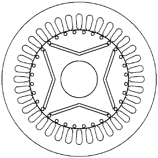
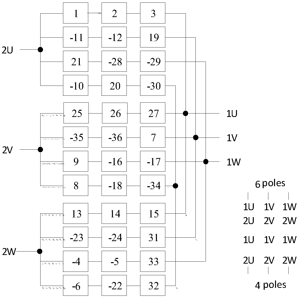
[0029] The new pole-changing speed-regulating permanent magnet motor in the present invention is composed of a stator pole-changing winding and a permanent magnet rotor with a cage winding, see figure 1 . Among them, the pole-changing winding can adopt a single-winding pole-changing scheme, that is, a set of pole-changing windings that can correspond to at least two different pole numbers th...


PUM


Abstract

The invention discloses a pole-changing speed-adjusting permanent magnet motor, comprising a rotating shaft, a stator iron core and a rotor iron core which surround the rotating shaft and used for cooperating with each other; the stator iron core is provided with a stator slot; pole-changing winding is installed in the stator slot; in addition, a permanent magnet is arranged inside the rotor ironcore. The variable pole winding is used to provide at least two different pole numbers, in particular at least two independent sets of variable pole winding with different pole logarithms, or a set ofvariable pole winding is transformed by its wiring mode to correspond to at least two different pole numbers. The invention improves the component structure of the whole motor and the cooperation working mode between each component, especially by improving the setting of stator pole-changing winding and the corresponding pole-changing mode, the novel variable pole speed permanent magnet motor isobtained. Compared with the variable pole induction motor, the novel variable pole speed permanent magnet motor improves the efficiency and power factor, and solves a series of problems such as complex structure, high cost and high difficulty in pole-changing process control of the existing pole-changing speed-adjusting permanent magnet motor.

Description

technical field [0001] The invention belongs to the field of motors, and more specifically relates to a pole-changing speed-regulating permanent magnet motor, which is a permanent magnet synchronous motor capable of asynchronous starting and pole-changing speed regulation. Background technique [0002] Today, energy shortage has become an important issue related to human survival, and it is imperative to develop new energy and save energy. Electric energy is currently the most widely used secondary energy by human beings, and it is closely related to the national energy conservation, emission reduction and sustainable development strategies. With the development of the country's economy, industrial electricity consumption has increased year by year, accounting for more than 70% of the country's electricity consumption, and the electricity consumption of motors accounts for more than 50% of the total industrial electricity consumption. Therefore, the energy saving of motors ...

Claims


Application Information

Patent Timeline
IPC IPC(8): H02K21/14H02K21/04H02K19/12
CPCH02K19/12H02K21/042H02K21/14
Inventor 王晋徐雷敏周理兵
Owner HUAZHONG UNIV OF SCI & TECH
Learn More