Eureka AIR delivers breakthrough ideas for toughest innovation challenges, trusted by R&D personnel around the world.

Delay calibration output device and method

An output device and delay chain technology, which is applied to synchronization devices, transmission systems, digital transmission systems, etc., can solve the problems of high delay value calibration cost, delay value calibration accuracy and delay value measurement efficiency, etc., and achieve the realization cost. low, high measurement efficiency

Active Publication Date: 2019-01-11
上海星秒光电科技有限公司 +1
View PDF5 Cites 3 Cited by
  • Summary
  • Abstract
  • Description
  • Claims
  • Application Information

AI Technical Summary

Problems solved by technology

However, this kind of delay value calibration scheme requires high delay value calibration cost, and the corresponding delay value calibration accuracy and delay value measurement efficiency are not high

Method used


Image

  • Delay calibration output device and method
  • Delay calibration output device and method
  • Delay calibration output device and method

Examples


Embodiment Construction

[0026] In order to make the purposes, technical solutions and advantages of the embodiments of the present application clearer, the technical solutions in the embodiments of the present application will be clearly and completely described below in conjunction with the drawings in the embodiments of the present application. Obviously, the described embodiments It is a part of the embodiments of this application, not all of them. The components of the embodiments of the application generally described and illustrated in the figures herein may be arranged and designed in a variety of different configurations.

[0027] Accordingly, the following detailed description of the embodiments of the application provided in the accompanying drawings is not intended to limit the scope of the claimed application, but merely represents selected embodiments of the application. Based on the embodiments in this application, all other embodiments obtained by persons of ordinary skill in the art w...


PUM


Abstract

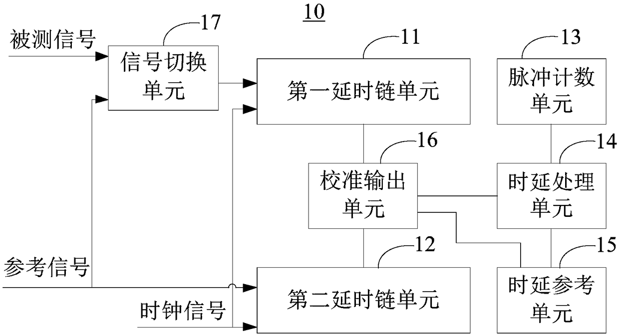
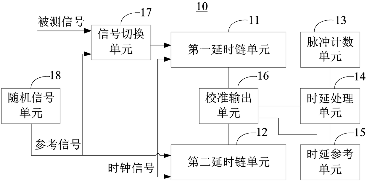
The present invention provides a delay calibration output device and method. The device comprises a first delay chain unit, a second delay chain unit, a pulse counting unit, a delay processing unit, adelay reference unit and a calibration output unit. The first delay chain unit is configured to transmit detected signals and generate first transmission data; the second delay chain unit is configured to transmit the reference signals and generate second transmission data; the pulse counting unit is configured to obtain counting data of the second delay chain unit; the delay processing unit is configured to obtain actual delay data according to the clock signals and the counting data of the second delay clock unit; the delay reference unit stores first reference delay data and second reference delay data; and the calibration output unit is configured to calibrate and output a delay value corresponding to the first delay chain unit at present according to the first reference delay data, the second reference delay data, the actual delay date, the second transmission data and the first transmission data. The device is low in delay calibration cost and high in delay calibration accuracy.

Description

technical field [0001] The present application relates to the technical field of delay value calibration, and in particular, to a delay calibration output device and method. Background technique [0002] In the existing Time-to-Digital Converter (TDC) based on FPGA (Field-Programmable Gate Array, Field-Programmable Gate Array), the method of measuring the rough time of the measured signal and adding fine time is generally used To obtain the transmission time of the signal under test, the coarse time can be obtained by directly counting the system clock signal, and the fine time is usually obtained by measuring the delay of the signal under test based on the internal delay chain structure of the FPGA. However, since the delay value of the delay chain inside the FPGA will change with the change of temperature and / or voltage, if the measured delay value is not calibrated, measurement deviation will occur. [0003] At present, the mainstream in the industry usually calibrates t...

Claims


Application Information

Patent Timeline
Patent Type & Authority Applications(China)
IPC IPC(8): H04L7/00
CPCH04L7/0037H04L7/0041
Inventor 张帅陈杰
Owner 上海星秒光电科技有限公司
Why Eureka
Eureka Blog
Learn More