
Intelligent automatic organic fertilizer spreading machine

A technology of spreader, organic manure

Active Publication Date: 2019-01-15
重庆坤载农业科技有限公司
View PDF4 Cites 0 Cited by
  • Summary
  • Abstract
  • Description
  • Claims
  • Application Information

AI Technical Summary

Problems solved by technology

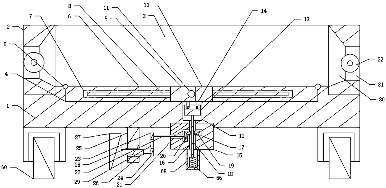
[0004] The object of the present invention is to overcome the problems existing in the prior art, and to provide an automatic agricultural organic manure spreader, which can arrange the organic manure in the tank of the carriage, so that the organic manure can be transported by using the floor of the carriage. During the sliding process of the carriage floor, the main rotating shaft provided by the carriage side plates on both sides can be rotated to further drive the rotation of the discharge runner, so that the organic manure in the carriage tank can be spread by the discharge runner, thereby The rotation of the discharge runner can be used to further throw out the organic manure, so that the uniform spreading of the organic manure can be realized, and the discharge runner can swing in the discharge port, so that the discharge can be further ensured The effect of spreading the organic manure by the runner can squeeze the organic manure through the extrusion plate set in the compartment groove during the sliding process of the carriage floor, so as to further ensure the discharge effect of the organic manure, and in the compartment There is a lifting and lowering device on the bottom plate, which can control the lifting of the squeezing plates on both sides through the lifting and lowering device, so that the squeezing plates on both sides can continuously squeeze the organic manure, thereby further Ensure the discharge effect of the discharge runner, so as to avoid the problem of uneven artificial spreading of organic manure, further improve work efficiency, and further reduce the workload

Method used


Image

  • Intelligent automatic organic fertilizer spreading machine
  • Intelligent automatic organic fertilizer spreading machine
  • Intelligent automatic organic fertilizer spreading machine

Examples


Embodiment Construction

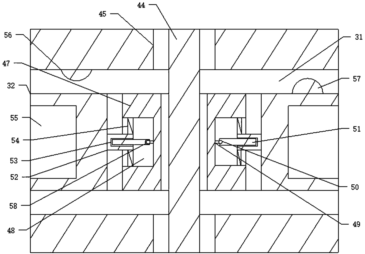
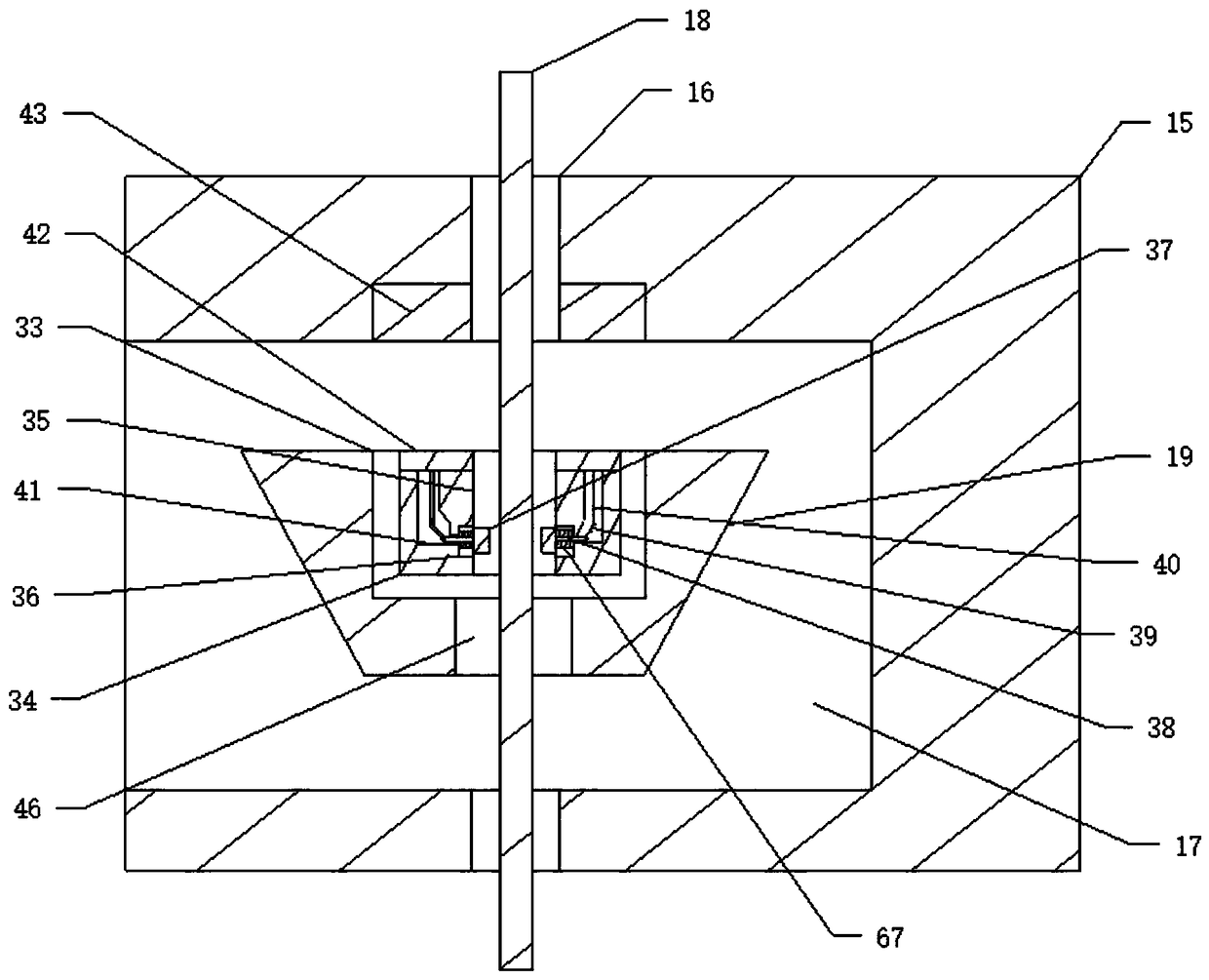
[0031] like Figure 1 to Figure 9 As shown, an automatic agricultural organic manure spreader includes a carriage floor 1, a second roller 60 is respectively arranged on both sides of the carriage floor 1, and a carriage side plate 2 is respectively connected to both sides of the carriage floor 1. The compartment side plate 2 and the compartment bottom plate 1 form a compartment trough 3, and a row of discharge openings 31 corresponding to the compartment trough 3 are respectively arranged on the compartment side plates 2 on both sides. A main shaft 44 that rotates in the discharge port 31 is respectively arranged in the side panel 2 of the carriage, and a discharge runner 32 that rotates in the discharge port 31 is respectively arranged on the main shaft 44 . The material runner 32 swings in the mouth of the discharge 31, and a compartment side plate 2 is respectively connected to both sides of the compartment floor 1, and an inner groove is formed between the compartment flo...


PUM


Abstract

The invention discloses an intelligent automatic organic fertilizer spreading machine. Two sides of a carriage base plate are respectively connected to one carriage lateral plate. Two carriage lateralplates and the carriage base plate form a carriage groove. The carriage lateral plates are both provided with a row of discharge openings that are communicated with the carriage groove. Main rotationshafts that rotate in the discharge openings are arranged in the carriage lateral plates. Each main rotation shaft is provided with one discharge rotation wheel that rotates in one discharging opening; the discharge rotation wheel swings in the discharging opening; the carriage base plate is also provided with a first groove that is communicated with the carriage groove; two sides of the first groove are both provided with a rotation extrusion plate; two extrusion plates are corresponding to the discharge openings; an organic fertilizer can be sprayed out through the rotation of the dischargerotation wheels; the labor strength is reduced, and the uneven fertilizing caused by artificial operation is avoided.

Description

technical field [0001] The invention relates to an agricultural fertilizer spreader, in particular to an automatic agricultural organic manure spreader, in particular to an agricultural organic manure spreader capable of uniformly spreading land and increasing the spreading area. Background technique [0002] With the continuous development of science and technology, it has further promoted the continuous innovation of agricultural machinery. Among them, spreading fertilizer is one of the indispensable links in the current agricultural planting, so that the production of food can be further increased through fertilization. The harm to the human body is very great, so more and more organic manure is used in the agricultural production process. Most of the current organic manure fertilization processes are artificially fertilized, because the manure is easy to lead to sticky manure during the fermentation process. Because of the problem of clumps, it can only be fertilized man...

Claims


Application Information

Patent Timeline
Patent Type & Authority Applications(China)
IPC IPC(8): A01C3/06
CPCA01C3/06
Inventor 不公告发明人
Owner 重庆坤载农业科技有限公司
Learn More