A remotely controlled infusion device with a controllable flow rate

A technology of remote control and infusion device, applied in the direction of flow control, non-electric variable control, control/regulation system, etc. It can solve the problems of inconvenient adjustment process and inability to control the flow rate accurately, so as to achieve the effect of remote control

Inactive Publication Date: 2019-01-15
THE FIRST AFFILIATED HOSPITAL OF WENZHOU MEDICAL UNIV
View PDF6 Cites 5 Cited by
  • Summary
  • Abstract
  • Description
  • Claims
  • Application Information

AI Technical Summary

Problems solved by technology

[0004] However, the existing adjustable flow rate structure is to set a box-shaped shell on the infusion tube, open an adjusting groove on one side of the shell, and open a groove opposite to the adjusting groove on the groove wall of the adjusting groove. There is a sliding groove extending obliquely on the wall, and a roller is set in the adjusting groove. Rollers are coaxially fixed at both ends of the roller, and the rollers are rollingly connected in the sliding groove. Therefore, during the rolling process of the rollers, the distance between the rollers and the bottom of the adjustment groove is constantly changing due to the rolling of the rollers in the sliding groove, so the extent to which the rollers squeeze the infusion tubes is also different. , this effectively achieves the effect of adjusting the infusion flow rate of the infusion tube. However, this method needs to be adjusted by pushing the rollers by hand, so it is impossible to achieve a more precise control of the flow rate. At the same time, a nurse is required during the adjustment process. Or other people can only adjust when they reach the position of the infusion tube, which also makes the adjustment process inconvenient

Method used


Image

  • A remotely controlled infusion device with a controllable flow rate
  • A remotely controlled infusion device with a controllable flow rate
  • A remotely controlled infusion device with a controllable flow rate

Examples


specific Embodiment approach

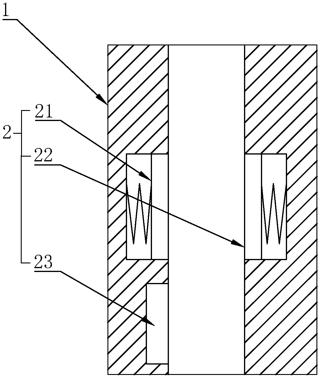
[0027] As an improved specific implementation manner, the drive circuit 23 includes:

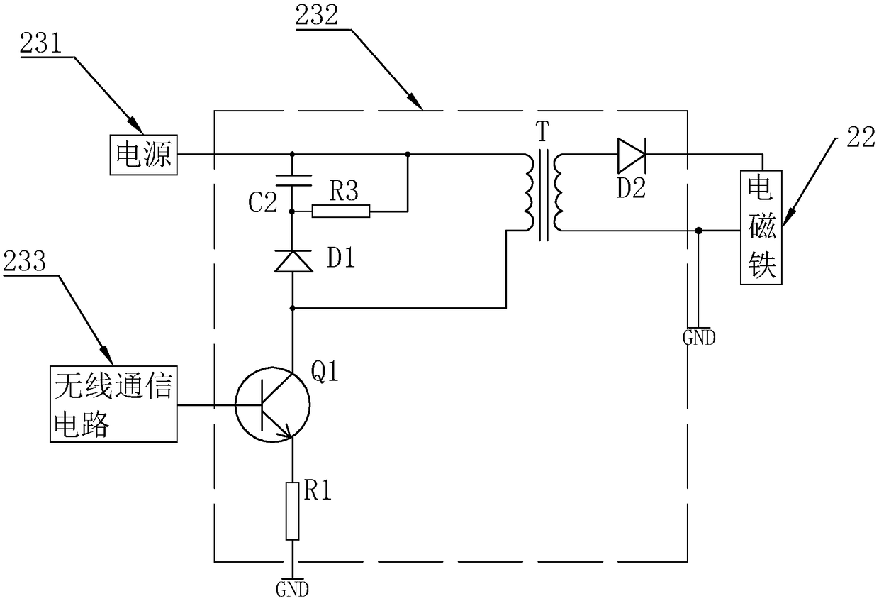
[0028] The power supply 231 is arranged on the casing 1 and coupled with the electromagnet 22 to apply a voltage to the electromagnet 22 to generate a magnetic force;

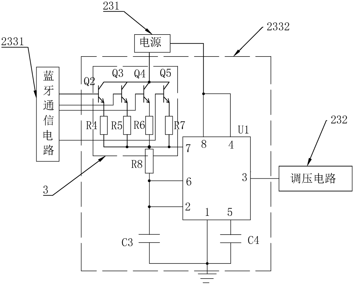
[0029] A voltage regulating circuit 232, coupled between the power supply 231 and the electromagnet 22, for adjusting the voltage applied by the power supply 231 to the electromagnet 22;

[0030]The wireless communication circuit 233 is coupled to the voltage regulating circuit 232, and is also coupled to the external smart phone, so as to receive the signal output by the external smart phone and send the signal to the voltage regulating circuit 232, and control the voltage regulating circuit 232 to adjust the voltage applied to the electromagnet 22. Through the setting of the power supply 231, an electromagnet 22 can effectively provide a power supply for generating magnetic force, and through the setting of the voltage regu...


PUM


Abstract

The invention discloses a remotely controlled infusion device with a controllable flow rate, including a housing sleeved on the infusion tube and a flow rate adjusting mechanism disposed within the housing, the flow rate adjusting mechanism comprises a magnetic plate and an electromagnet and a driving circuit, the magnetic sheet and the electromagnet are respectively elastically and fixedly connected with opposite two sides in the shell and cooperate with each other to clamp an infusion pipe. The driving circuit is electrically connected with an electromagnet to drive the electromagnet to generate a magnetic attracting magnetic sheet. The driving circuit is also wirelessly connected with an external smartphone to generate a magnetic force after receiving a signal outputted from the external smartphone. The infusion device of the invention can effectively control the infusion flow rate of the infusion pipe through an external smartphone by setting a housing and a flow rate adjusting mechanism, and by setting the flow rate adjusting mechanism into a magnetic sheet and an electromagnet.

Description

technical field [0001] The invention relates to an infusion device, and more specifically relates to a remote-controlled infusion device with controllable flow rate. Background technique [0002] Infusion is a relatively curative means of disease treatment in the prior art. Through infusion therapy, the medicine can take effect as quickly as possible, and it has a significant curative effect on acute symptoms such as fever caused by relatively serious colds. [0003] The infusion speed in the infusion is determined according to the patient's physical condition and the condition of the drug, so that the drug can achieve the best curative effect in the shortest time after the infusion, so the existing infusion devices have the function of adjustable flow rate . [0004] However, the existing adjustable flow rate structure is to set a box-shaped shell on the infusion tube, open an adjusting groove on one side of the shell, and open a groove opposite to the adjusting groove on ...

Claims


Application Information

Patent Timeline
Patent Type & Authority Applications(China)
IPC IPC(8): A61M5/168
CPCA61M5/16813A61M5/16877A61M2205/3334
Inventor 项俊之
Owner THE FIRST AFFILIATED HOSPITAL OF WENZHOU MEDICAL UNIV
Why Eureka
Try Eureka