
Environment-friendly machine for solid waste treatment

A solid waste, environmentally friendly technology, applied in the field of machinery, can solve the problems of inability to achieve multiple bases, collision of two rolling rollers, affecting processing efficiency, etc. The effect of efficiency

Inactive Publication Date: 2019-01-15
姚冬冬
View PDF5 Cites 0 Cited by
  • Summary
  • Abstract
  • Description
  • Claims
  • Application Information

AI Technical Summary

Problems solved by technology

[0003] 1. The traditional solid waste treatment device has a large volume and high production cost, which is not easy to promote and use, resulting in a small scope of application, and cannot work in multiple bases. Garbage trucks are required to transport solid waste to distant bases ;
[0004] 2. After the traditional solid waste treatment device grinds and crushes solid waste, it needs to be transferred to other equipment for secondary treatment. The workload of transferring waste is relatively large and affects its treatment efficiency;
[0005] 3. The traditional solid waste treatment device uses cylinders to adjust the distance between the rolling rollers, and there is no limit structure between the two rolling rollers, which will easily cause the two rolling rollers to collide, and under the violent push of the cylinder, the increase The wear between the rolling roller and the rolling frame, and the lack of a buffer structure may easily cause the rolling frame to shake

Method used

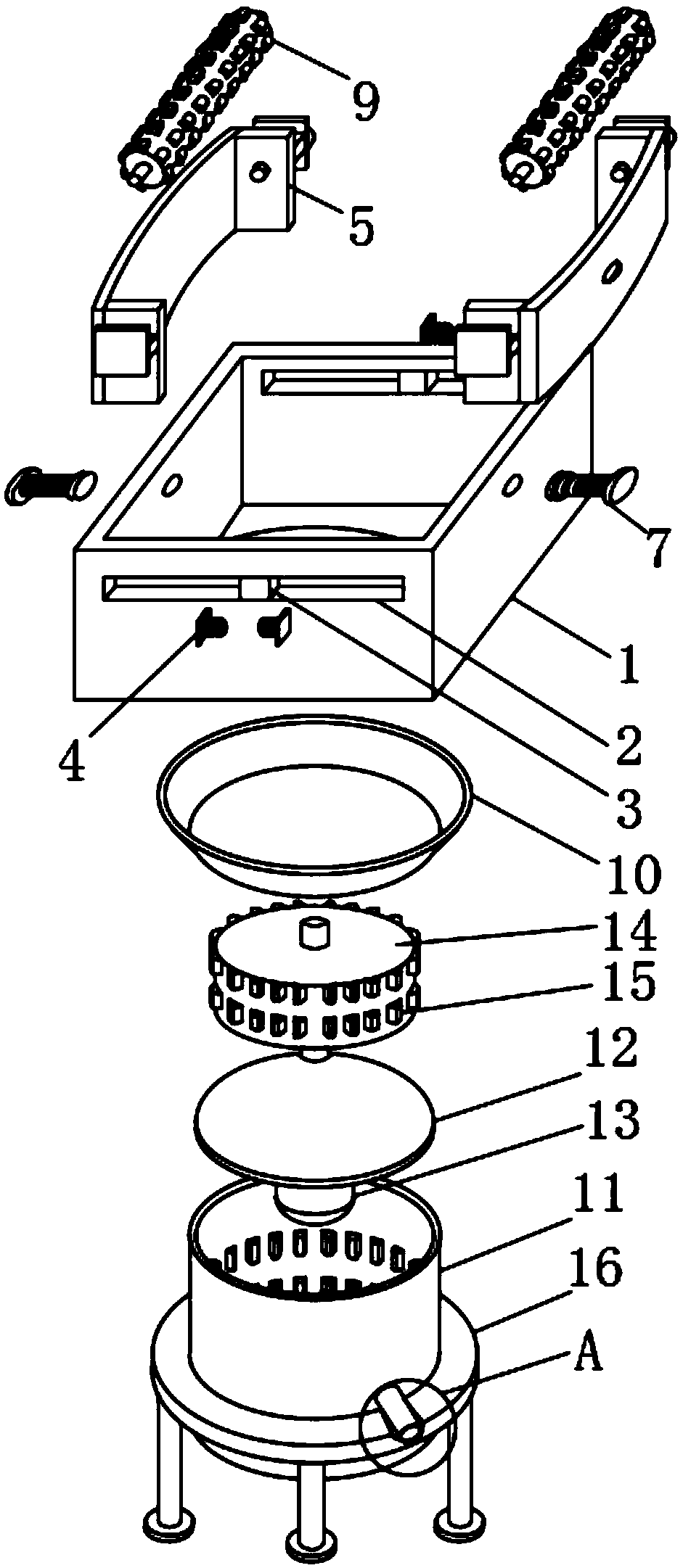

Image

  • Environment-friendly machine for solid waste treatment
  • Environment-friendly machine for solid waste treatment
  • Environment-friendly machine for solid waste treatment

Examples


Embodiment Construction

[0023] The following will clearly and completely describe the technical solutions in the embodiments of the present invention with reference to the accompanying drawings in the embodiments of the present invention. Obviously, the described embodiments are only some, not all, embodiments of the present invention. Based on the embodiments of the present invention, all other embodiments obtained by persons of ordinary skill in the art without making creative efforts belong to the protection scope of the present invention.

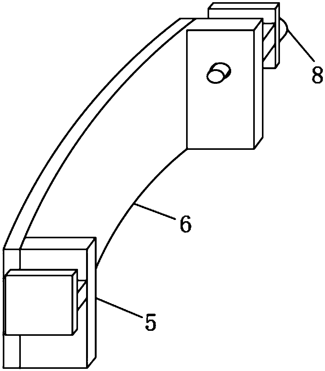
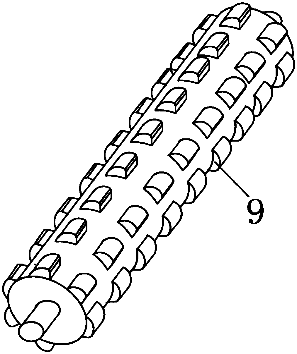
[0024] see Figure 1-5 , the present invention provides a technical solution: an environmental protection machine for solid waste treatment, comprising a rolling frame 1, a rolling roller 9, a crushing cylinder 11 and a bearing plate 16, the surface of the rolling frame 1 is provided with a guide groove 2, The middle part of the guide groove 2 is fixedly connected with a partition block 3, the surface of the partition block 3 is fixedly connected with a buffer...


PUM


Abstract

The invention discloses an environment-friendly machine for solid waste treatment. The machine comprises a grinding frame, grinding rollers, a smashing cylinder and a bearing plate; guide grooves areformed in the surface of the grinding frame, separation blocks are fixedly connected to the middles of the guide grooves, buffer parts are fixedly connected to the surfaces of the separation blocks, two limiting plates are in sliding connection into the guide grooves, connecting plates are fixedly connected between two limiting plates, rotation grooves are formed in the faces of the connecting plates, adjusting rods are rotatably connected into the rotation grooves, the adjusting rods are in screw joint to side plates of the grinding frame, the adjusting rods penetrate through the outer wallsof the side plates of the grinding frame, a first motor is fixedly connected to the surface of the limiting plate on one side, the adjusting rods are arranged on the grinding frame, and the adjustingrods can stably adjust the connecting plates; the interval between the two grinding rollers is good in controllability, the buffer parts are arranged on the grinding frame, collision between the two grinding rollers is avoided, and the vibration amplitude during adjusting of the grinding rollers can be reduced.

Description

technical field [0001] The invention relates to the field of mechanical technology, in particular to an environmental protection machine for solid waste treatment. Background technique [0002] In the process of people's life and production, a large amount of waste is produced every day, and discarding the waste anywhere will pollute the land. Therefore, some environmental protection machines have appeared on the market for centralized treatment of solid waste, but they are still used in actual use. There are the following disadvantages: [0003] 1. The traditional solid waste treatment device has a large volume and high production cost, which is not easy to promote and use, resulting in a small scope of application, and cannot work in multiple bases. Garbage trucks are required to transport solid waste to distant bases ; [0004] 2. After the traditional solid waste treatment device grinds and crushes solid waste, it needs to be transferred to other equipment for secondar...

Claims


Application Information

Patent Timeline
IPC IPC(8): B02C21/00B02C4/08B02C4/32B02C4/10
CPCB02C4/08B02C4/10B02C4/32B02C21/00B02C2201/06
Inventor 姚冬冬王卓瑜苏越青
Owner 姚冬冬
Learn More