Water conservancy project pipeline dredging method

A technology for water conservancy projects and pipelines, which is applied to cleaning methods and appliances, chemical instruments and methods, and cleaning hollow objects, etc. It can solve the problems of pipeline silt accumulation and blockage, and achieve the effects of small equipment size, labor saving, and simple dredging process

Inactive Publication Date: 2019-01-15
闫丽娟
View PDF9 Cites 9 Cited by
  • Summary
  • Abstract
  • Description
  • Claims
  • Application Information

AI Technical Summary

Problems solved by technology

[0004] The purpose of the present invention is to solve the problem of silt accumulation inside the pipelines of water conservancy projects, leading to the problem of silt accumulation and clogging of pipelines, and to provide a method for dredging pipelines of water conservancy projects

Method used


Image

  • Water conservancy project pipeline dredging method
  • Water conservancy project pipeline dredging method
  • Water conservancy project pipeline dredging method

Examples


specific Embodiment approach 1

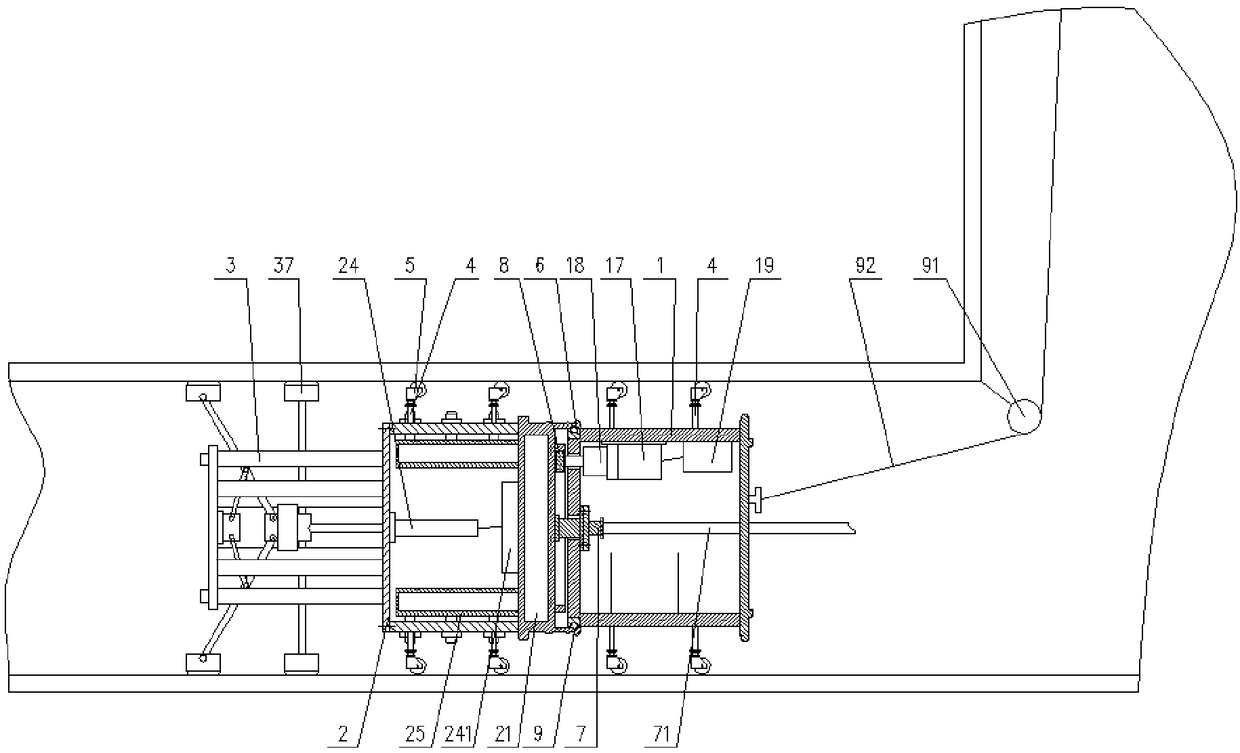
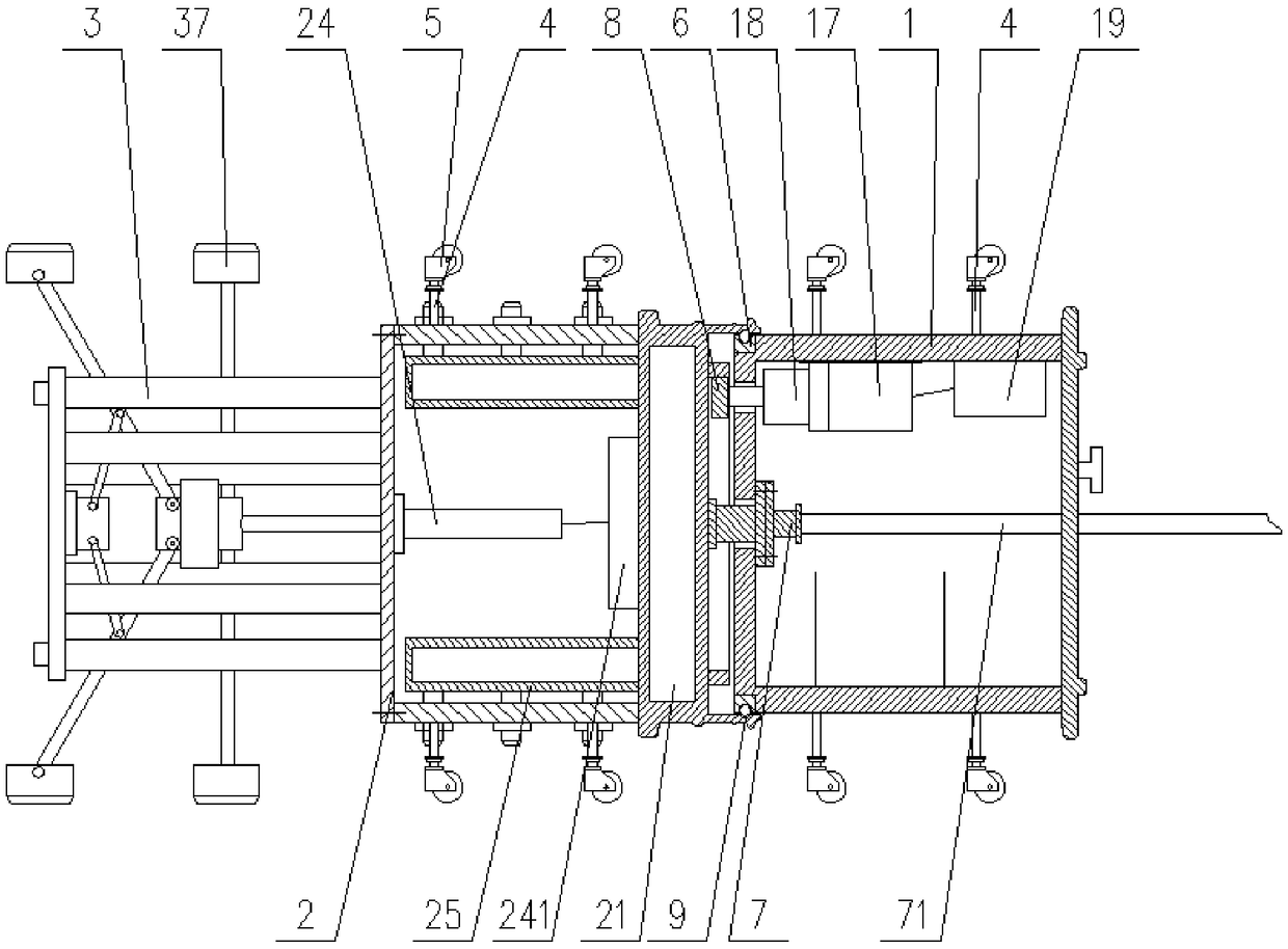
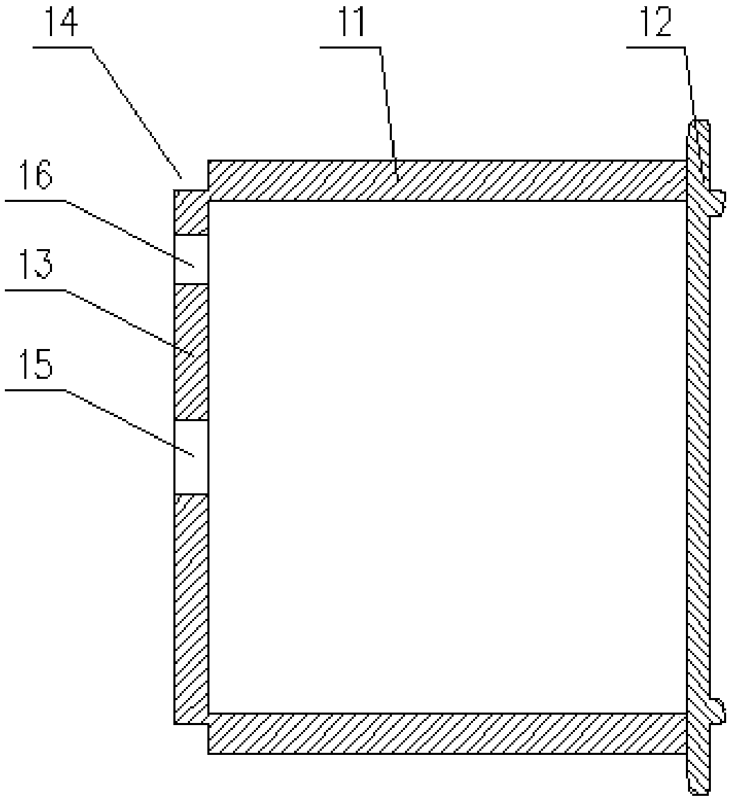
[0036] Specific implementation mode one: combine figure 1 and Figure 7Describe this embodiment, a water conservancy project pipeline dredging device in this embodiment, including a driving base 1, a pipeline sludge flushing device 2 and a pipeline washing device 3, the overall shape of the driving base 1 is cylindrical, and the outer wall of the driving base A support rod 4 is installed on the support rod 4, and a traveling wheel 5 is installed on the supporting rod 4. The traveling wheel 5 is a universal traveling wheel, and the driving base 1 includes a base housing 11 and a bottom cover 12. The base housing 11 The right end is an open structure, and a bottom cover 12 is installed on the right end of the base shell 11. An annular groove 14 is processed on the left side wall 13 of the base of the base shell 11, and an annular slide rail is installed in the annular groove 14. 6. The center position of the left side wall 13 of the base shell 11 is processed with a rotary adap...

specific Embodiment approach 2

[0038] Specific implementation mode two: combination figure 1 and Figure 7 Describe this embodiment, a water conservancy project pipeline desilting device in this embodiment, the pipeline sludge flushing device 2 includes a water storage box 21, a flushing installation box 22, a flushing installation box cover 23, an electric push rod 24, The flushing pipe 25 and the flushing head 26, the right side of the water storage box 21 are respectively provided with a slider 9 and an inner ring gear 10, and the water storage box 21 is connected to the rotating shaft installed in the center of the left side wall 13 of the base. The joint 7 is connected, and the left side of the water storage box 21 is connected with a plurality of flushing pipes 25. The flushing installation box 22 is welded and installed on the left side of the water storage box 21. The flushing pipes 25 are arranged in the flushing installation box. 22, a flushing head 26 is installed on the flushing pipe 25, and th...

specific Embodiment approach 3

[0040] Specific implementation mode three: combination figure 1 and Figure 7 Describe this embodiment, a water conservancy project pipeline desilting device of this embodiment, the right side of the water storage box 21 has a water inlet 211, and the rotation of the water inlet 211 and the center position of the left side wall 13 of the base The adapter 7 is connected, and the left side of the water storage box 21 has water outlets 212 in an annular array, and each water outlet 212 is sealed with a flushing pipe 25 . In this way, the water inlet 211 is used to communicate with the rotary adapter 7 , and the water outlet 212 is communicated with the flushing pipe 25 .


PUM


Abstract

The invention relates to a water conservancy project pipeline dredging method, and belongs to the technical field of water conservancy projects. The invention aims to solve the problem of sludge accumulation and blockage of the pipeline due to accumulation of sludge inside the water conservancy project pipeline. The method comprises the following steps of 1, placing a water conservancy project pipeline dredging device into a pipeline to be cleaned; step 2, flushing the interior of the water pipe into high-pressure water, so that the water in the water pipe is filled into the water storage tankand is filled with the flushing pipe; step 3, starting the driving motor, driving the motor to drive the pipeline sludge flushing device, and scattering the sludge in the pipeline; step 4, starting an electric push rod to carry out scrubbing operation on the pipeline; step 5, repeating the step 2 to the step 5 until the whole pipeline is subjected to dredging operation, closing the power source of the dredging device, and evacuating the dredging device from the pipeline. By means of the method, the scrubbing operation can be carried out in the pipeline, so that the silt inside the pipeline can be cleaned up, the dredging effect is good, and the reliability is high when using.

Description

technical field [0001] The invention relates to a water conservancy engineering pipeline dredging method, which belongs to the technical field of water conservancy engineering. Background technique [0002] Pipeline dredging refers to dredging the pipeline, cleaning up the silt and other wastes in the pipeline, and keeping it unblocked for a long time to prevent urban waterlogging. If the pipeline is not regularly dredged, it will cause excessive sewage flow, pollute the environment, and bring troubles to people's lives. [0003] In our real life, dredging the inner wall of water conservancy engineering pipelines is generally done manually. This method requires a large amount of labor, increases the cost of dredging, and is time-consuming and laborious. Reduce work efficiency, and the accumulation of sludge and waste in water conservancy pipelines for a long time will produce toxic gases. When construction personnel work in water conservancy pipelines for a long time, it wil...

Claims


Application Information

Patent Timeline
Patent Type & Authority Applications(China)
IPC IPC(8): B08B9/043B08B9/045B08B9/047
CPCB08B9/0433B08B9/0436B08B9/045B08B9/047
Inventor 闫丽娟
Owner 闫丽娟
Why Eureka
Try Eureka