Distilled water generator

A distilled water and generator technology, applied in the field of equipment for generating distilled water, can solve the problems of less distilled water and power consumption, and achieve the effects of less scale, less energy consumption, and increased output

Inactive Publication Date: 2019-01-15
广东安然食品科技有限公司
View PDF0 Cites 1 Cited by
  • Summary
  • Abstract
  • Description
  • Claims
  • Application Information

AI Technical Summary

Problems solved by technology

[0004] However, tap water contains impurities, which will generate scale and deposit on the outer surf

Method used


Image

  • Distilled water generator
  • Distilled water generator

Examples


Embodiment Construction

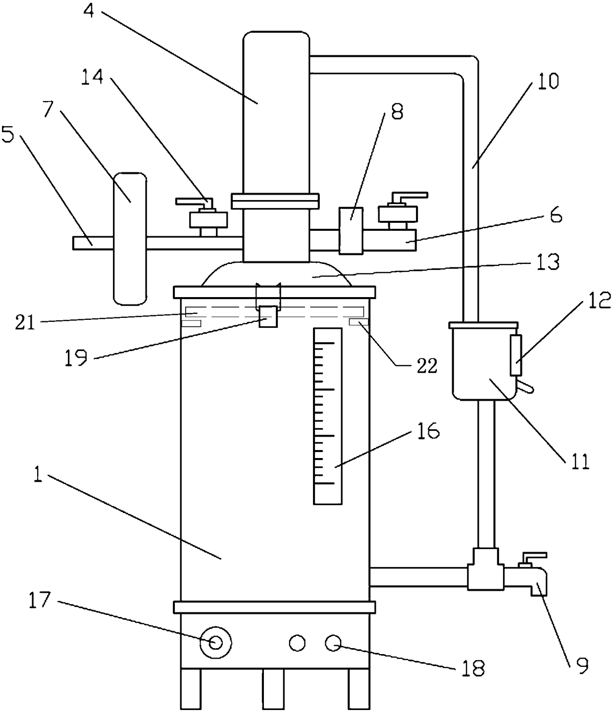
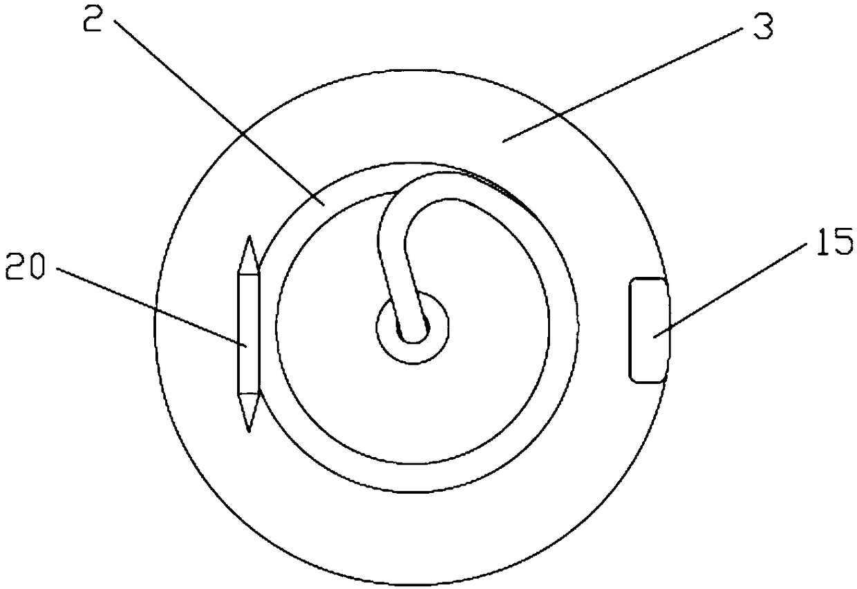
[0022] Such as figure 1 and figure 2 As shown, one of the embodiments provided by the present invention is a distilled water generator, including a tank body 1, a first heating tube 2 is arranged at the bottom of the tank body 1, and an evaporation chamber 3 is arranged above the first heating tube 2 , the top of the tank body 1 is provided with a condenser 4 .

[0023] In order to solve the problem of increased energy consumption and reduced output of distilled water after depositing scale on the first heating tube 2, a second heating tube 21 and a bracket 22 supporting the second heating tube 21 are arranged on the top of the tank body 1, and the second heating tube 21 and bracket 22 are arranged in the tank body 1 .

[0024] In this embodiment, on the basis of setting the first heating tube 2 at the bottom of the tank body 1, a second heating tube 21 and a bracket 22 supporting the second heating tube 21 are set on the top of the tank body 2, thereby forming two-stage he...


PUM


Abstract

The invention discloses a distilled water generator. The distilled water generator comprises a tank body, wherein the bottom of the tank body is provided with a first heating pipe; an evaporation chamber is formed above the first heating pipe; a condenser is arranged on the top of the tank body; a second heating pipe and a bracket supporting the second heating pipe are arranged on the top of the tank body; the second heating pipe and the bracket are arranged in the tank body. By adopting the distilled water generator, energy consumption can be lowered, and the output of distilled water is increased.

Description

technical field [0001] The invention relates to equipment for generating distilled water, in particular to a distilled water generator. Background technique [0002] The distilled water generator uses the principle of liquid preheating to vaporize and liquefy when it is cold. It uses electric heating of tap water to produce pure water by distillation. It can be used in medical and health, pharmaceutical, electroplating and laboratory departments. [0003] The structure of the currently used distilled water generator mainly includes a tank body, a heating tube is arranged at the bottom of the tank body, and the heating tube is used to heat tap water to generate distilled water. [0004] However, tap water contains impurities, which will generate scale and deposit on the outer surface of the heating tube to block heat dissipation, consume more power, and produce less distilled water. Contents of the invention [0005] In order to overcome the above problems, the present inv...

Claims


Application Information

Patent Timeline
IPC IPC(8): C02F1/04
CPCC02F1/04
Inventor 林吉渠
Owner 广东安然食品科技有限公司
Why Eureka
Try Eureka