Muddy water circulating system for shield tunneling machine

A technology of shield machine and muddy water, applied in mining equipment, earthwork drilling, tunnels, etc., can solve problems such as inability to discharge slurry, poor flow, and easy accumulation of mud and slag in the air cushion warehouse, so as to prevent the stagnation of slag and soil, The effect of reducing the specific gravity and reducing the risk of surface breakdown or subsidence

Pending Publication Date: 2019-01-15
CHINA RAILWAY TUNNEL GROUP CO LTD +1
View PDF13 Cites 9 Cited by
  • Summary
  • Abstract
  • Description
  • Claims
  • Application Information

AI Technical Summary

Problems solved by technology

[0006] The technical problem to be solved by the present invention is to provide a muddy water circulation system of the shield machine, which solves the problem in the prior art that the air cushion chamber of the muddy water shield machine is easy to accumulate mud and slag, resulting in poor slag discharge and unable to directly discharge slurry from the muddy water chamber question

Method used


Image

  • Muddy water circulating system for shield tunneling machine
  • Muddy water circulating system for shield tunneling machine
  • Muddy water circulating system for shield tunneling machine

Examples


Embodiment 1

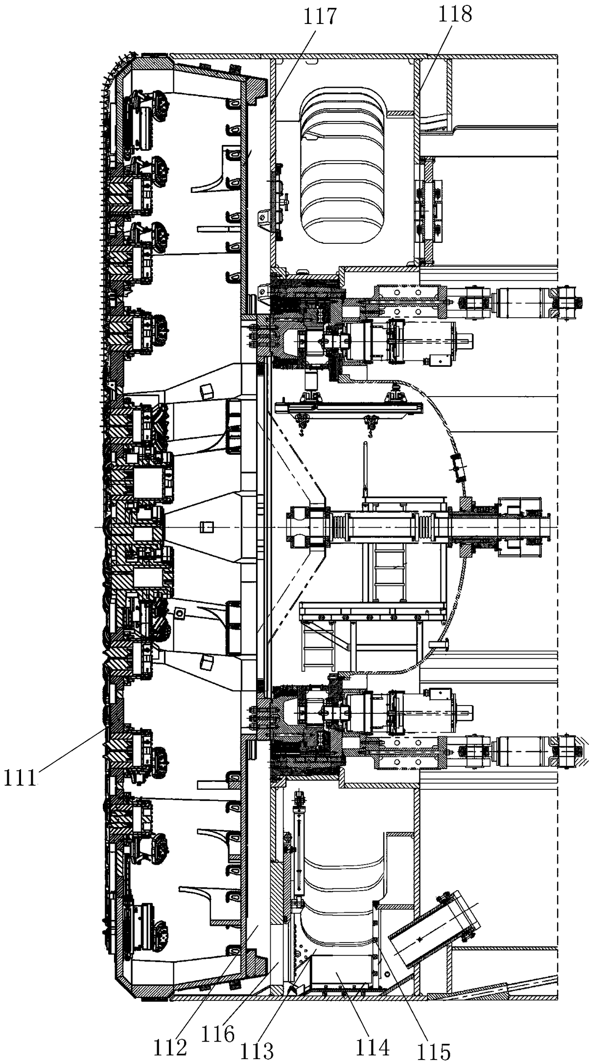
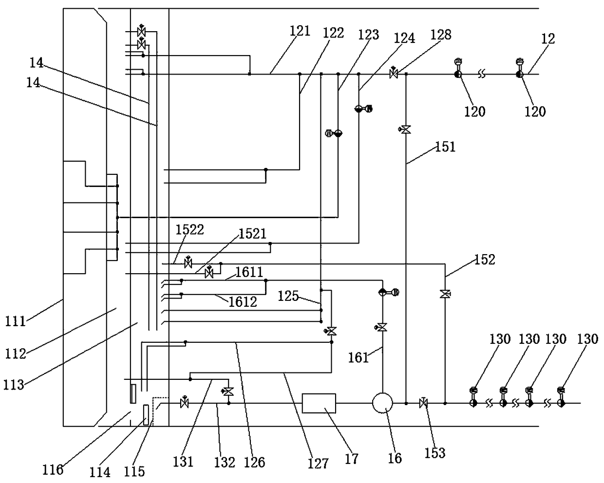
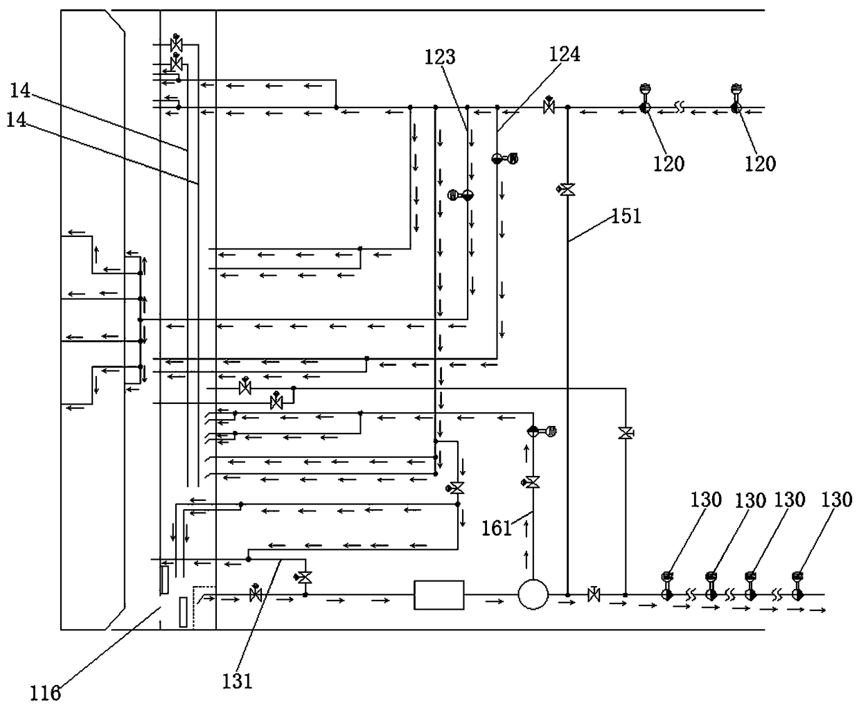
[0033] see Figure 1 to Figure 6 .

[0034] Such as figure 1 As shown, the mud-water circulation system of the shield machine provided by the embodiment of the present invention is used on the mud-water balance shield machine. The rear of the cutterhead 111 of the mud-water balance shield machine is isolated by the front partition 117 and the rear partition 118. Two internal spaces, Wherein, before the front bulkhead 117 is the mud tank 112, between the front bulkhead 117 and the rear bulkhead 118 is the air cushion warehouse 113, the bottom of the front bulkhead 117 is provided with a mud door 116, and the mud in the mud water bin 112 is passed through the mud door. 116 enters the air cushion warehouse 113, the upper half of the air cushion warehouse 113 is filled with pressurized air, the lower half of the air cushion warehouse 113 is mud, and the slurry discharge pipeline discharges the mud in the lower half of the air cushion warehouse 113 outwards, at the bottom of the a...


PUM


Abstract

The invention discloses a muddy water circulating system for a shield tunneling machine. The muddy water circulating system for the shield tunneling machine comprises a main slurry inlet pipeline anda main slurry discharging pipeline, wherein the tail end of the main slurry discharging pipeline is communicated with a muddy water cabin slurry discharging branch pipe and an air cushion cabin slurrydischarging branch pipe; both the muddy water cabin slurry discharging branch pipe and the air cushion cabin slurry discharging branch pipe are provided with valves; the elevation of the tail end ofthe muddy water cabin slurry discharging branch pipe is higher than that of the tail end of the air cushion cabin slurry discharging branch pipe. The muddy water cabin slurry discharging branch pipe and the air cushion cabin slurry discharging branch pipe can be opened separately. In a normal tunneling process, muddy water slurry is discharged through the air cushion cabin slurry discharging branch pipe. When discharge of muck in a muddy water cabin is hindered, a slurry door is closed, the valve on the air cushion cabin slurry discharging branch pipe is switched off while the valve on the muddy water cabin slurry discharging branch pipe is switched on, and the muddy water in the muddy water cabin is discharged directly through the muddy water cabin slurry discharging branch pipe, so thatthe slurry circulating strength in the muddy water cabin is enhanced, the residue carrying capability is enhanced, prevention of muck discharge hindering is facilitated greatly, the slurry content ofthe muddy water cabin is lowered, and the probability of mud lining on a cutterhead is lowered.

Description

technical field [0001] The invention relates to the technical field of a mud-water balance shield machine, in particular to a mud-water circulation system of a shield machine. Background technique [0002] The mud-water balance shield machine is equipped with a front closed partition on the rear side of the cutter head of the mechanical shield (the bottom of the front closed partition is a mud door with an opening, and the upper part is provided with an exhaust pipeline connected to the atmosphere and The valve is used to discharge the gas in the mud tank), the space between the front closed partition and the cutter head is the mud tank, and the mud made by mixing water, bentonite and its additives is pressed into the mud tank through the pumping pipeline. Another rear closed partition is inserted in the rear side of the closed partition (the bottom of the rear closed partition is provided with an outlet for discharging mud). Through the mud door set at the bottom of the fr...

Claims


Application Information

Patent Timeline
Patent Type & Authority Applications(China)
IPC IPC(8): E21D9/06E21D9/13
CPCE21D9/06E21D9/13
Inventor 梁奎生陈建立刘旭郝超超唐纵雄董祥宽杨洋
Owner CHINA RAILWAY TUNNEL GROUP CO LTD
Why Eureka
Try Eureka