Impeller locking device for centrifugal compressor

A centrifugal compressor and locking device technology, applied in the field of compressors, can solve the problems of complex structure, low impeller strength, inconvenient operation, etc., and achieve the effects of reducing processing stress, improving assembly technology, and reducing damage

Pending Publication Date: 2019-01-15
四川聚亿重工有限公司
View PDF13 Cites 2 Cited by
  • Summary
  • Abstract
  • Description
  • Claims
  • Application Information

AI Technical Summary

Problems solved by technology

In actual use, although this patent can achieve the expected locking force more accurately, it still has the defects of relatively complicated structure and inconvenient operation.
[0004] In the actual use of this patent, although the expected locking force can be achieved more accurately, it still has the defects of relatively complex structure, low impeller strength and inconvenient operation.

Method used


Image

  • Impeller locking device for centrifugal compressor
  • Impeller locking device for centrifugal compressor
  • Impeller locking device for centrifugal compressor

Examples


Embodiment 1

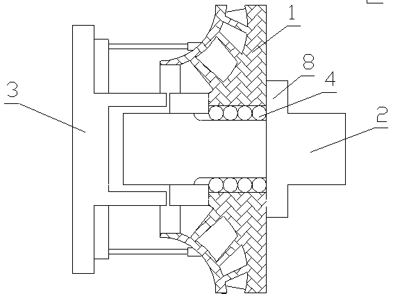
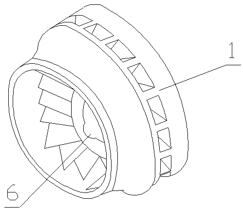
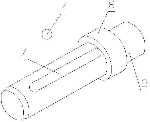
[0035] As a most basic implementation of the present invention, the present embodiment discloses an impeller locking device for a centrifugal compressor, such as figure 1 — Figure 5 As shown, it includes an impeller 1, a main shaft 2, a base 3, a key 4 and a lock nut 5. The inner wall of the shaft hole of the impeller 1 is provided with an impeller keyway 6, and the outer surface of the main shaft 2 is provided with an impeller keyway 6. Corresponding to the main shaft keyway 7, the radial sections of the impeller keyway 6 and the main shaft keyway 7 are smooth curves, the main shaft 2 includes a threaded end and a shoulder end, the threaded end is provided with external threads, and the shaft shoulder A shaft shoulder 8 is provided on the end, a seat body 9 and a hydraulic jack 10 are arranged on the base 3, and an action ring 11 applied to the force of the lock nut 5 is arranged in the middle of the seat body 9, and the hydraulic jack 10 is symmetrical Arranged on both sid...

Embodiment 2

[0038] As a preferred embodiment of the present invention, this embodiment discloses an impeller locking device for a centrifugal compressor, such as figure 1 — Figure 5 As shown, it includes an impeller 1, a main shaft 2, a base 3, a key 4 and a lock nut 5. The inner wall of the shaft hole of the impeller 1 is provided with an impeller keyway 6, and the outer surface of the main shaft 2 is provided with an impeller keyway 6. Corresponding to the main shaft keyway 7, the radial sections of the impeller keyway 6 and the main shaft keyway 7 are smooth curves, the main shaft 2 includes a threaded end and a shaft shoulder end, the threaded end is provided with external threads, and the shaft shoulder A shaft shoulder 8 is provided on the end, a seat body 9 and a hydraulic jack 10 are arranged on the base 3, and an action ring 11 applied to the force of the lock nut 5 is provided in the middle of the seat body 9, and the hydraulic jack 10 is symmetrical Arranged on both sides of ...


PUM


Abstract

The invention discloses an impeller locking device for a centrifugal compressor, and belongs to the field of compressors. The impeller locking device comprises an impeller, a main shaft, a base, a keyand a locking nut. An impeller keyway is arranged on the inner wall of the shaft hole of the impeller, and a main shaft keyway corresponding to the impeller keyway is arranged on the outer surface ofthe main shaft, and the radial cross sections of the impeller keyway and the main shaft keyway are smooth curves. The main shaft includes a threaded end and a shoulder end, wherein the threaded end is provided with an external thread, the shoulder end is provided with a shoulder, and the base is provided with a seat body and hydraulic jacks. The middle part of the seat body is provided with an action ring applying force on the locking nut, and the hydraulic jacks are symmetrically disposed on both sides of the seat body. The top end of each hydraulic jack is fixedly provided with a top blockacting on the outer ring of the impeller, and the inner part of the locking nut is provided with an internal thread matched with the external thread. The impeller locking device has the advantages ofmore convenient locking, less damage to the locking nut and improvement of the strength of the impeller.

Description

technical field [0001] The invention belongs to the field of compressors, in particular to an impeller locking device for centrifugal compressors. Background technique [0002] At present, the impeller of centrifugal compressors mostly adopts the structure of double-key connection, but for the structure of fastening connection with pre-tightened bolts, how to ensure the expected locking force in the process has become a difficult problem in the assembly process. The traditional process method is to tighten the lock nut with a torque wrench. This method is laborious to operate, and the size of the pre-tightening force is not easy to grasp, and it is easy to cause the fit between the lock nut and the impeller shaft to be too tight or too loose. [0003] The prior art with Chinese patent announcement number "CN201377466" disclosed a locking device for centrifugal compressor impeller on January 6, 2010. The technical solution is: the impeller includes an impeller shaft and a thr...

Claims


Application Information

Patent Timeline
Patent Type & Authority Applications(China)
IPC IPC(8): F04D29/28F04D29/62
CPCF04D29/266F04D29/284F04D29/624
Inventor 王小龙白永贵赵成
Owner 四川聚亿重工有限公司
Why Eureka
Try Eureka