
A method of constructing 3D mesh model of large underground engineering under complex geological conditions

A complex geological condition and grid model technology, applied in the field of 3D grid model construction, can solve the problems of time-consuming and laborious establishment of 3D grid model for large underground engineering, complex shape of 3D geometric model, poor quality of grid division, etc. Achieve the effects of reducing modeling workload, reducing the total number of grid units, and ensuring grid quality

Inactive Publication Date: 2019-01-15
INST OF ROCK AND SOIL MECHANICS - CHINESE ACAD OF SCI +2
View PDF4 Cites 6 Cited by
  • Summary
  • Abstract
  • Description
  • Claims
  • Application Information

AI Technical Summary

Problems solved by technology

[0002] The current 3D numerical analysis method has become a common method for the stability of surrounding rock in large-scale underground engineering, but the construction of 3D grid models for large-scale underground engineering under complex geological conditions has become a major obstacle to the popularization and application of this method. The specific difficulties are reflected in : 1) The geometric shape of the underground structure is complex, and the intersection with the discontinuous surface often causes the entire 3D geometric model to be cut into a large number of small and complex areas, resulting in poor grid quality; 2) Large-scale underground engineering excavation, Staged / layered / step-by-step excavation is usually adopted, and the discontinuous surface actually revealed is often different from the distribution of the discontinuous surface obtained in the previous survey. It is necessary to repeatedly adjust its position and geometric shape, rebuild the geometric model and subdivide the grid, making the establishment of such a large-scale underground engineering 3D grid model time-consuming and laborious

Method used


Image

  • A method of constructing 3D mesh model of large underground engineering under complex geological conditions
  • A method of constructing 3D mesh model of large underground engineering under complex geological conditions

Examples


Embodiment 1

[0034] see figure 1 , in this software, the core command flow to realize step 5 is: group f1 ran plane dd 191dip 48 ori 271.769050, 734.759597, 2264 dist 1.0 group 35, the italics in the command flow are command keywords, and the subsequent parameters can be changed according to the actual situation. The situation is modified, the meaning of this command is: the group name is 35 points (271.769050, 734.759597, 2264), the inclination angle of 191°, the inclination angle of 48°, and the grids within the distance of 1.0m above and below the normal direction of the plane are returned to for group f1. According to this command format, you can continue to add other occurrences of discontinuous surfaces in the constructed FLAC3D3D mesh model.

Embodiment 2

[0036] see figure 2 , in this software, the specific steps to realize step five are:

[0037] ① Create key points: K, NPT1, X1, Y1, Z1; ... K, NPT2, X2, Y2, Z2; NPT3, X3, Y3, Z3 (any 3 points in the discontinuous plane can be taken, NPT1- NPT3 is the number of the point, X1-X3, Y1-Y3, Z1-Z3 are the coordinates of the point, which can be modified according to the actual situation);

[0038] ②Move the working plane: KWPLAN, WN, NPT1, NPT2, NPT3 (move the working plane to the above key point, and its Z axis is parallel to the normal direction of the discontinuous surface);

[0039] ③Create a local coordinate system: CSWPLA, 11, 0, 1, 1, (Create a local coordinate system with the coordinate system number 11 based on the coordinate origin of the above work plane as the origin. The number can be modified according to the actual situation, but the value must be greater than or equal to 11) ;

[0040] ④ Activate the current local coordinate system: CSYS, 11,;

[0041] ⑤ Select th...


PUM


Abstract

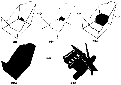
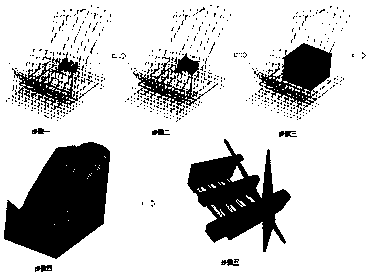
The invention relates to the technical field of 3D mesh model construction. The invention particularly relates to a method for constructing a 3D mesh model of a large-scale underground engineering under complex geological conditions, comprising the following steps: firstly, constructing or importing a geometric model of a excavated body with a relatively regular shape according to a point, a lineand a surface in other data formats in a mesh generation software ANSYS; and secondly, constructing a 3D mesh model of the excavated body according to the geometric model. 2, establishing a partitionbody with a certain range and simple geometrical shape around the excavation body as a key analysis area; Step 3: outside the key analysis area, delimiting a simple and regular separator as the secondary key concern area, and the mesh can be roughly divided appropriately. The invention has the advantages that: in the excavation process of layered, step-by-step and subsection, if the previously unknown discontinuous surface occurs or the occurrence of the known discontinuous surface changes, the method can change the original 3D mesh model in time without re-establishing / updating the geometricmodel and then dividing the mesh to establish the 3D mesh model.

Description

technical field [0001] The invention relates to the technical field of 3D grid model construction, in particular to a construction method of a large-scale underground engineering 3D grid model under complex geological conditions. Background technique [0002] The current 3D numerical analysis method has become a common method for the stability of large-scale underground engineering surrounding rock, but the construction of 3D grid models for large-scale underground engineering under complex geological conditions has become a major obstacle to the popularization and application of this method. The specific difficulties are reflected in : 1) The geometric shape of the underground structure is complex, and the intersection with the discontinuous surface often causes the entire 3D geometric model to be cut into a large number of small and complex areas, resulting in poor grid quality; 2) Large-scale underground engineering excavation, Staged / layered / step-by-step excavation is us...

Claims


Application Information

Patent Timeline
Patent Type & Authority Applications(China)
IPC IPC(8): G06T17/05G06T17/20
CPCG06T17/05G06T17/20
Inventor 徐鼎平李邵军黄翔江权汪斌张家新樊波
Owner INST OF ROCK AND SOIL MECHANICS - CHINESE ACAD OF SCI
Learn More