
An orthotropic piezoelectric ceramic actuator

A piezoelectric ceramic and orthotropic technology, applied in the field of orthotropic piezoelectric ceramic drives, can solve the problems of poor driving directionality and small driving force, and achieve the effects of low cost, reduced cost and difficulty, and novel structure

Active Publication Date: 2019-01-15
HENAN UNIV OF SCI & TECH
View PDF9 Cites 4 Cited by
  • Summary
  • Abstract
  • Description
  • Claims
  • Application Information

AI Technical Summary

Problems solved by technology

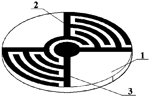
[0003] Aiming at the defects of small driving force and poor driving directionality of piezoelectric ceramic drivers in the prior art, the purpose of the present invention is to provide an orthotropic piezoelectric ceramic driver, which can obtain a larger micro-scale by using a larger piezoelectric constant d33 Displacement and driving force, at the same time have the characteristics of orthotropy, strong directionality

Method used


Image

  • An orthotropic piezoelectric ceramic actuator
  • An orthotropic piezoelectric ceramic actuator
  • An orthotropic piezoelectric ceramic actuator

Examples

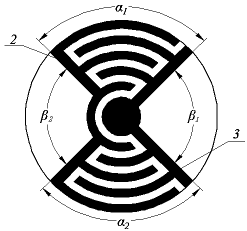
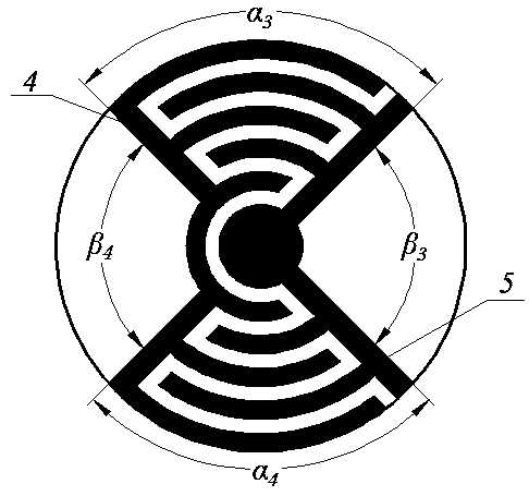

Embodiment Construction

[0025] The present invention will be described in further detail below in conjunction with the accompanying drawings and specific embodiments.

[0026] The orthotropic piezoelectric ceramic driver of the present invention includes a piezoelectric ceramic substrate 1 and electrodes covered on the upper and lower surfaces of the piezoelectric ceramic substrate, and the electrodes on each surface include electrode one (2, 4) and electrode two ( 3, 5), the lower surface electrode and the upper surface electrode are arranged completely symmetrically with respect to the middle plane in the thickness direction of the piezoelectric ceramic, the upper surface electrode one 2 and the lower surface electrode one 4 are connected to form electrode pair I, the upper surface electrode two 3 and the lower surface electrode two The surface electrodes 2 and 5 are connected to form electrode pair II. Electrodes 1 (2, 4) and electrodes 2 (3, 5) are fan-shaped interdigitated electrodes. Electrodes ...


PUM


Abstract

The invention relates to an orthotropic piezoelectric ceramic actuator, comprises a circular piezoelectric ceramic substrate and a piezoelectric ceramic substrate covered with the circular piezoelectric ceramic substrate, an electrode on the lower surface, A low surface electrode and an upper surface electrode are arranged symmetrically with respect to an intermediate surface in that thickness direction of the piezoelectric ceramic, the electrodes on each surface comprise an electrode 1 and an electrode 2, the electrode 1 and the electrode 2 are fan-shaped interdigital electrodes, the electrodes 1 and 2 on the same surface are arranged in a cross arrangement with each other, A surface of that piezoelectric ceramic is for with two fan-shaped electrode regions, As that angle of the electroderegion can be adjust according to the actuation range of the actuator, The directional angle can be adjusted according to the actuation direction of the actuator, and the large displacement output inthe specific direction or the stress wave signal with high energy generated in the specific direction can be realized by the invention, especially suitable for the micro-actuation field, so that theprecision can be improved and the realization difficulty of the precision equipment can be reduced.

Description

technical field [0001] The invention relates to the field of piezoelectric ceramic driving technology, in particular to an orthotropic piezoelectric ceramic driver. Background technique [0002] With the rapid development of modern industry, the requirements for high-precision mechanical engineering micro-drivers are getting higher and higher; piezoelectric ceramic drives have the advantages of high resolution, fast response, small size, and large driving force, and have been widely used in the field of micro-drives application. However, the commonly used piezoelectric ceramic driver works in the d31 mode. Due to the small driving displacement, the piezoelectric ceramic driver array must be used, or the method of increasing the external power supply voltage is used to increase the output of the driver, and the structure is complicated; at the same time, due to the in-plane The isotropic characteristics of piezoelectric ceramics generate stress waves of equal intensity in al...

Claims


Application Information

Patent Timeline
Patent Type & Authority Applications(China)
IPC IPC(8): H01L41/047H01L41/09H01L41/29H10N30/87H10N30/06H10N30/20
CPCH10N30/87H10N30/206H10N30/06
Inventor 刘永刚曹胜捷吴舟贾其苏张婷张浩男郭全圆
Owner HENAN UNIV OF SCI & TECH
Learn More