
electrical connector

A technology for electrical connectors and connections, which is applied in the direction of conductive connections, connections, vehicle connectors, etc., and can solve problems such as reducing wires, poor electrical contact, and disconnected wires

Active Publication Date: 2021-06-29
TE CONNECTIVITY ITAL DISTRIBUTION SRL
View PDF7 Cites 0 Cited by
  • Summary
  • Abstract
  • Description
  • Claims
  • Application Information

AI Technical Summary

Problems solved by technology

[0003] However, due to the current tendency to reduce the size of the wires increasingly (about 0.046mm in thickness), this technique has a range of possible disadvantages such as broken wires, or poor electrical contact if the wires are not properly insulated

Method used


Image

  • electrical connector
  • electrical connector
  • electrical connector

Examples


Embodiment Construction

[0035] The description that follows shows various specific details intended to provide an improved understanding of the embodiments. Embodiments may be practiced without one or more of the specific details, or using different methods, components, materials, etc. In other instances, known structures, details of construction, materials or operations are not shown or described in detail because they may be implemented in any known manner and because they would not be within the scope of the invention when considered in isolation.

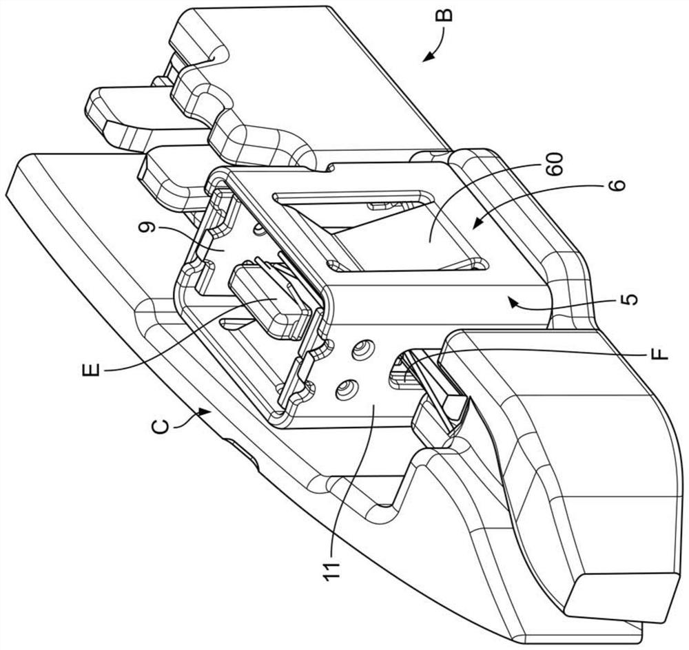
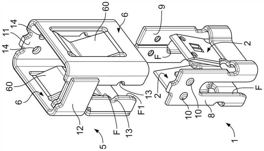
[0036] In the drawings, reference sign C denotes a preferred embodiment of the electrical connector according to the present invention. exist figure 1 , connector C is connected to the magnetic ignition coil B of the internal combustion engine. In a conventional production process, the connector C is obtained by cutting to a suitable size and bending a sheet metal plate. The details of the construction relating to the manufacturing process of the ig...


PUM


Abstract

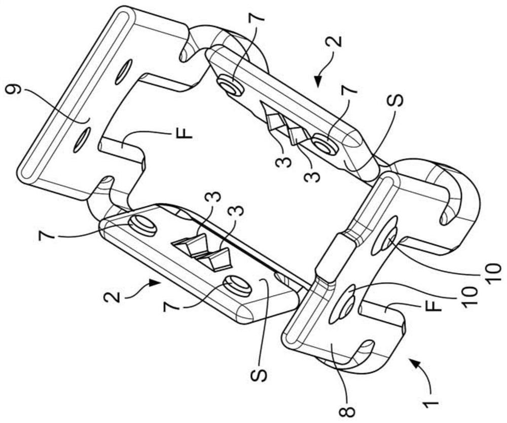
An electrical connector for connection to a magnetic ignition coil of an internal combustion engine. The coil comprises wire and the object has a covering of insulating material and is wound on a support element. The electrical connector includes contact elements made of electrically conductive material, the lead elements being coupleable to the support element. The contact element has two flexible walls facing each other and diverging outwards and adapted to come into contact with the support element. A cutting element is located on at least one of the flexible walls on its inner surface facing the support element and is adapted to cut into the insulating material covering of the wire. The connector also includes a flexible sleeve mountable over and around the contact elements to retain the contact elements on the support element. A flexible sleeve is located above said contact element and is movable relative to the contact element, after the contact element has been fitted over the support element, into a final operative position, in the final operative position.

Description

technical field [0001] The invention relates to an electrical connector for connection to a magnetic ignition coil of an internal combustion engine. More specifically, the connector according to the invention forms a connection with an insulated microcable having a winding on a support element fitted in the motor head. The connector is arranged in electrical contact with the insulated microcable of the winding of the coil. As a result, the connector is configured to be positioned in the motor head and to withstand the shock, vibration and high temperatures generated by the operating steps of the internal combustion engine with which the connector is associated. Background technique [0002] In established technology, the connection to an ignition coil for an internal combustion engine, in which a support element is arranged on which the wires are wound, is made by welding after partial removal of the insulating varnish layer covering the wires. [0003] However, due to the...

Claims


Application Information

Patent Timeline
Patent Type & Authority Patents(China)
IPC IPC(8): H01R4/2416H01R13/02H01R13/40
CPCH01R4/2416H01R13/02H01R13/40H01R4/2433H01R4/48H01R13/2407H01R4/2404H01R2201/26H01R4/70
Inventor A.金塔M.法里诺拉
Owner TE CONNECTIVITY ITAL DISTRIBUTION SRL
Learn More