
Cabinet for power distribution

A power distribution cabinet and cabinet door technology, which is applied in the substation/distribution device shell, electrical components, substation/switch layout details, etc., to achieve the effect of convenient maintenance, avoiding heavy rain and good use effect.

Inactive Publication Date: 2019-01-15
XINXIANG POWER SUPPLY COMPANY STATE GRID HENAN ELECTRIC POWER +3
View PDF0 Cites 0 Cited by
  • Summary
  • Abstract
  • Description
  • Claims
  • Application Information

AI Technical Summary

Problems solved by technology

[0004] The purpose of the present invention is to overcome the deficiencies of the power distribution cabinet in the prior art, and solve the inconvenience problems encountered by engineers when using the power distribution cabinet as much as possible, so as to provide a distribution cabinet with simple structure, convenient maintenance and good use effect. electric cabinet

Method used


Image

  • Cabinet for power distribution
  • Cabinet for power distribution
  • Cabinet for power distribution

Examples


Embodiment Construction

[0015] The present invention will be further described below in conjunction with the accompanying drawings.

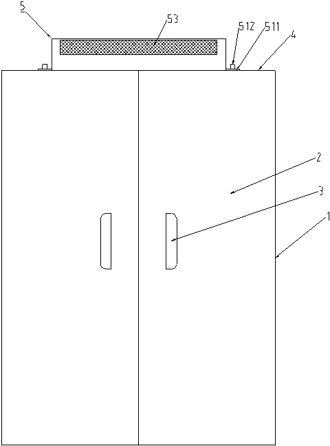
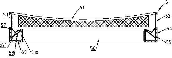
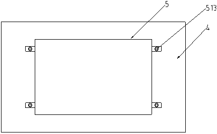
[0016] Such as Figure 1-Figure 3 As shown, a power distribution cabinet includes a side wall 1, a cabinet door 2 and a top cover 4. The cabinet door 2 is symmetrically provided with a handle 3, and the center of the top cover 4 is provided with a first ventilation hole. A ventilation device 5 is arranged above the cover 4, and the ventilation device 5 includes a concave cover plate 51, a side plate 54 and a bottom plate 59. The upper part of the side plate 54 is provided with a rectangular ventilation hole 52, and the lower part is symmetrically provided with a first drainage The holes 55 are covered with a layer of filter screen 53 on the inner side of the rectangular ventilation holes 52, and the inner bottom of the side plate 54 is symmetrically provided with a V-shaped baffle 57, and the bottom of the V-shaped baffle 57 is provided with several second drainage hol...


PUM


Abstract

A switch cabinet including sidewalls, Cabinet door and top cover, A handle is symmetrically arrange on that cabinet door, a ventilating device is arranged above the top cover, the ventilation device comprises a concave cover plate, Side and bottom panels, the upper part of the side plate is provided with a rectangular ventilation hole, A low part is symmetrically provided with a first drain hole,A lay of filter screen is cover on that inner side of the rectangular vent, A V-shaped baffle is symmetrically arranged at the bottom of the inner side of the side plate, a plurality of second asphaltholes are arranged at the bottom of the V-shaped baffle, a partition plate is arranged below the V-shaped baffle, four fixing plates are symmetrically arranged at the inner side of the V-shaped baffle plate, the fixing plates are enclosed to form a second ventilation hole, and a fan is arranged in the second ventilation hole; The outer bottom of the side plate is provided with a fixing piece, thecentral position of the fixing piece is provided with a threaded hole, and a cylindrical stopper is arranged above the threaded hole. Generally speaking, the invention has the advantages of simple structure, convenient maintenance and good use effect.

Description

technical field [0001] The invention relates to the technical field of power distribution equipment, in particular to a power distribution cabinet. Background technique [0002] Power distribution cabinet is to assemble switchgear, measuring instrument, protective device and auxiliary equipment in a closed or semiclosed metal cabinet or on a screen width according to the requirements of electrical wiring to form a low-voltage power distribution device, which can be operated by manual or automatic switch during normal operation. Connect or break the circuit, cut off the circuit or alarm with the help of protective electrical appliances in case of failure or abnormal operation. In addition, the power distribution cabinet also needs good waterproof and heat dissipation capabilities. [0003] In the currently disclosed technical solutions, several heat dissipation holes are generally provided on the side wall of the power distribution cabinet, or a cooling fan is installed on th...

Claims


Application Information

Patent Timeline
Patent Type & Authority Applications(China)
IPC IPC(8): H02B1/30H02B1/56H02B1/28
CPCH02B1/30H02B1/28H02B1/565
Inventor 姚猛李胜亚王海明王新铭袁正兵李明李霞王斌
Owner XINXIANG POWER SUPPLY COMPANY STATE GRID HENAN ELECTRIC POWER
Learn More